Digital Link Input is not working properly

Ramil.R

Member
Join Date
Feb 2022
Location
Baku
Posts
2
Hello,

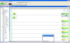
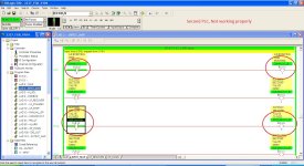
We have two identical SLC 500 PLCs, one for each package. Part of the programs of one of them is not working properly. Both projects are identical except for tag numbers.
So, Digital Link Input is not working properly in the second PLC (image 2). The coil does not react when its contact's corresponding bit has a value of 1. It only happens in the Digital Link Input parts of INPUT_MAP.
Could anyone help me why it happens?

Thanks in advance

First PLC.JPG Second PLC.JPG
 
It could be that the output bits are used elsewhere do a cross reference, as the link bits are shown as true it could be those output bits are being turned off elsewhere or the call to that block is not being enabled.
 
Welcome to the PLCTalk forum community ! Are you really in Azerbaijan or was that an accident of alphabetization when you registered ?

I agree that the two most likely explanations are a duplicate address conflict or that LAD3 is not being called by a JSR (Jump to Subroutine) instruction.

In the SLC-500 operating system, only LAD2 is automatically executed when the controller powers up. Every other LADx program file has to be executed by a Jump to Subroutine (JSR) instruction or be triggered by a feature like a Discrete Input Interrupt or a Selectable Timed Interrupt.

Right-click on either the input or output address and select "Cross Reference" to look for duplicate address conflicts.

To easily find the JSR that refers to the LAD3 subroutine, type "U:3" in the Search field in the Standard Toolbar at the top of the RSLogix 500 window, and click the Find All button.

FindU3.PNG
 
Welcome to the PLCTalk forum community ! Are you really in Azerbaijan or was that an accident of alphabetization when you registered ?

I agree that the two most likely explanations are a duplicate address conflict or that LAD3 is not being called by a JSR (Jump to Subroutine) instruction.

In the SLC-500 operating system, only LAD2 is automatically executed when the controller powers up. Every other LADx program file has to be executed by a Jump to Subroutine (JSR) instruction or be triggered by a feature like a Discrete Input Interrupt or a Selectable Timed Interrupt.

Right-click on either the input or output address and select "Cross Reference" to look for duplicate address conflicts.

To easily find the JSR that refers to the LAD3 subroutine, type "U:3" in the Search field in the Standard Toolbar at the top of the RSLogix 500 window, and click the Find All button.


Thank you very much. I am new to this forum and happy about this:). There is useful information. Thanks for being the creator of such kind of forum.
Yes, I am from Azerbaijan).
LAD3 is being called by a JSR instruction and in LAD3 only "Digital Link Input" instructions do not work properly but there is no problem with "digital input"

JSR.JPG Digital Input.JPG DIGITAL LINK input.JPG
 
Last edited:
Post your .RSS file if you can. Zip it first then post.

Someone may spot something in your program.
 
Right-click on N18:10/0 ( or /1 or /2) and select Cross-Reference.

Do the same on B3:101/0 (or /1 or /2).

The most likely problem is something writing over those addresses. Maybe it's at the word or file level (like that MOV does on Rung 8) or bitwise in additional OTE or OTU instructions elsewhere in the program.

Check also for any "Temporary End" (TND) or "Return from Subroutine" (RET) instructions earlier in the LAD3 routine.

Ladder logic with XIC and OTE is about the simplest thing that a PLC does. If the program logic is being executed, and there is nothing writing over those same addresses, then they *must* work.
 

Similar Topics

Question to anyone with ideas about my thoughts on upgrading a very vintage timer, which is being used to switch between 2 5hp domestic water...
Replies
14
Views
439
I have a PLC type PM856 from ABB with some I/O modules and I get an error from the Digital Inputs model type DI801. The unit status shows error...
Replies
0
Views
266
I am monitoring two BMXDDO3202K digital outputs for their behaviour, they are each for opening and closing, and so the on time affects how far the...
Replies
1
Views
287
On the laser displacement sensor now connected to my PLC, the manual says 4mA=643 and 20mA=64,877. However, I checked with a Fluke, injecting...
Replies
5
Views
892
I'm new to S7/TIA. There's no devices connected to the PLC yet. I've got a laser measurement sensor (Micro-Epsilon optoNCDT 1220). From the...
Replies
18
Views
2,958
Back
Top Bottom