Siemens S7/TIA v16: How do I see the digital value of AI sensor (4-20mA)?...

Mas01

Member
Join Date
Oct 2020
Location
Leicester, England
Posts
1,109
I'm new to S7/TIA.
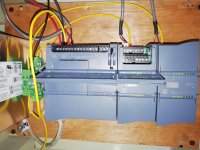
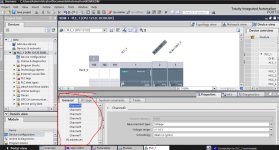
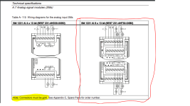
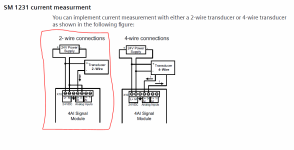
There's no devices connected to the PLC yet. I've got a laser measurement sensor (Micro-Epsilon optoNCDT 1220). From the paperwork, it's a 2-wire device (red +24V, White 0V current output, I think). My question is not so much about wiring it ( I have the diagram for that from the manual, see pic)...but if I physically connect it to Channel 0, how do I configure ch0 for a 4-20mA input (as opposed to say 0-5V) in the software? Ultimately, I want to measure the distance from the sensor head to the object directly in front of it, and monitor the value (at least the raw digital value) on TIA software. Thanks, and sorry for the basic question - I'll also see if there's any online videos w.r.t. this question.
Analogue Input module model.png Capture3.PNG IMG_20230615_142421.jpg IMG_20230615_142221.jpg
 
Last edited:
Wow, configuring the AI channels in S7 was painless compared to the ANALOGUES hex addressing/channel settings on Mitsubishi-Q.
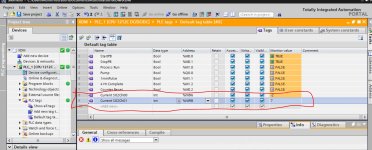
I need to inject a current from a Fluke or similar to test the range of values...4mA=0, 20mA=27,648.

Capture3.jpg
 
Wow, configuring the AI channels in S7 was painless compared to the ANALOGUES hex addressing/channel settings on Mitsubishi-Q.
I need to inject a current from a Fluke or similar to test the range of values...4mA=0, 20mA=27,648.


The PLC has Norm_X and Scale_X blocks to help you turn that into engineering units, by the way.


Norm_X takes a range and normalizes it to a real between 0.0 and 1.0, then Scale_X takes a value between 0.0 and 1.0 and scales it into whatever range you choose.


Or, ya know, you can math it out yourself. In theory, it's easy; in practice I usually have better things to do, and just use the blocks. Hint: If you're mathing it out yourself, you can add one rung of SCL via the right click menu, which is way simpler than trying to use a mishmash of add/mul/div/etc blocks.
Where's the 'Like' button when you need one? đź‘Ť

This Norm_x/Scale_x is music to my ears.
On Mitsubishi Q-series I was always implementing maths calcs as it doesn't support function blocks.
 
I need to inject a current from a Fluke or similar to test the range of values...4mA=0, 20mA=27,648.

You found the magic number!

To get an understandable number you need to create a network/rung with the following:
NORM_X ---> SCALE_X

NORM_X should have a 0 minimum, 27648 maximum and your %IW as the value, then create a conversion tag for the output which is a real data type so if you're using memory bits use %MD

SCALE_X should have your instrument range, whatever the scale of the signal is. Use your %MD conversion tag as the input and your output should be a new tag showing the scaled value from your instrument.

Not to complicate things, but I tend to use local tags for the conversion because it's never going to be used anywhere else in the program.

That's great info, cheers for this.
A basic question...the "I" in e.g. "%IW96" above stands for 'input', right? Just checking because Mitsubishi uses X and Y for input and output, respectively. Is "Q" for output in S7? Thanks
 
On TIA


%IW = Value is readed from process image which is updated before logic code scan.

%IWx :p = Value is readed directly from IO-card when logic code is asking it. (Same as PIW addressing on older Siemens Step7 logics, P = peripheral)


On TIA all IO's are readed to process image. (No need of peripheral read unless instant value is needed on code side)

On older PLCs process image was (usually) smaller than installed IO, so peripheral addressing was needed.
 
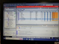
Hmmm, it didn't work when I connected a Fluke signal processor (Fluke 754).
I set up the Fluke to output 4mA and connected the leads to 0+ and 0- terminals (for channel 0). At 4mA, I got 32767 and it stayed at that value.
Anyone know what I'm doing wrong?
Thanks
Pictures to follow...

IMG_20230620_101303.jpg IMG_20230620_101333.jpg
 
Last edited:

Similar Topics

In OB1, I'm monitoring some values (first pic). The values are what I expect. At the same time, I'm monitoring the same values in the DB where...
Replies
1
Views
652
Siemens S7/TIA v16: "Overwrite if object exists online?" HMI loading message... Thus far, I've just been ticking this box, just to get the HMI...
Replies
4
Views
771
I'm having a bad day. Daft question coming up...Anyone know why I can't add anything into this DB? Add button is greyed-out. Thanks
Replies
14
Views
1,600
I imported a customised shape into the project, but I don't know how to actually add into on to a specific HMI screen. Do I use the Graphics menu...
Replies
2
Views
663
Hi I'm trying to display a value on the HMI. In monitor mode on the code, I can see that value, but on the HMI , after downloading, it is...
Replies
10
Views
949
Back
Top Bottom