Encoder Revolution Counter

afm

Member
Join Date
Aug 2023
Location
Tennessee
Posts
88
Hi all,

I am working with an incremental encoder (ABZ signals, 360 ppr (so 1440 counts per rev)) to replace the existing "manual" encoder wheel I have in my device. This is for a medical device with 2 footplates that cycle through steps via a linkage system, so 1 revolution = 1 stride = 2 steps (1 right and 1 left step)). My goal is to get total steps taken.

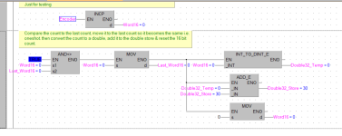
The way I was doing this is by taken total counts (EncoderPosition) and dividing by 720 (counts in half rev for one step). But when I do this I count up to 46, then this negates to -46 and counts back down and repeats. I believe this is because the module I am using for this sensor has max count of 32767, so it increments up to this value, negates, and counts back to 0.

I attached my relevant code, does anyone know a way to approach this given my count limit? Thanks in advance!

1709836274921.png

1709836306045.png
 
You have not said which PLC you are using I find it odd that the high speed input does not have at least 32 bit register, or have you used word integer type ? rather than a double integer. One way round it is when it reaches 32767 add that to a double (unsigned) word & reset the encoder register. then you can have
4294967295
 
Its a B&R X20CP0843 unit. The counter works a bit differently than the typical high speed counter as I am utilizing a X20MM4455 motor module for this that has counter functions, but its 16 bit. The EncoderPosition variable is INT type.

Will this method allow me to get a live update on my step counter? Currently, I can increment up to 46 steps, before it switched to -46 then repeats. So this will update the new double word register (lets call it TotalEncoderCounts) on every 46th step, right? I am currently doing the ActualPosition/720 to get the live steps taken, but since the TotalEncoderCounts will only update when ActualPosition is full, I cannot get the live total steps taken with my current method.
 
Not actually done it but we had a similar problem with a 16 bit word, it was pack counts reading into a Scada, the Function block was protected so could not change the data type to 32 bit double word so in the PLC I used a change of value on the16 bit, added it to tghe 32 bit reset the 16 bit word, so if the counts were faster than the scan time it would stay accurate so for instance assume we start at 0 for both 16 & 32 bit, the PLC on scan sees a change of 16 bit from 0 to say 2 (assume we get more than one pulse per scan) 2, add this to the 32 bit, reset the 16 bit.
 

Attachments

  • Count.png
    Count.png
    78.6 KB · Views: 14
Does the encoder input in the PLC have a Set or Reset?

On A-B at HCSE inputs there is a function to set the value to a specific value, say at a hoist passing a HOME sensor. Then the encoder count will be set to 00 or whatever value it is told to set to. I worked on a hoist that sensor was about 1/3rd the way down the track and set the count to about 2150 every time it passed when southbound. [I had to add the southbound only as the OEM had it both directions and taking differences of the 18mm prox and a 5/8" bolt hex head it would be off 3/4" after calibrating northbound.]

If this is possible then every time you count 1 step 000 the encoder
 
Configure the encoder to use the z pulse so it resets every revolution.
Find out if you are going forward or backward.
If you are going forwards then add two to the step counter every time the position is greater than some count (720) with a one-shot.
If reverse then decrement when lower
 
Hi all,

These are the
Does the encoder input in the PLC have a Set or Reset?
These are the confoguration options I have with my module's counter. I have a reset configured, but have not used it in my logic yet.

1710109751684.png

Thank you all for the suggestions, I haven't done anything like what was advised before, but I will try it out. What I was trying to do was use my ActualPosition variable which gives a readout ranging from 0-359 degrees. I attempted to do the following: Create ranges for degrees 0-179 and 180-359. On the positive transition of these ranges, increment a counter. However, the way I have it right now only increments when 180 degrees is passed, how can I adjust this to increment the counter when entering the 0-179 threshold?

1710110434814.png
I may have been oversimplifying my issue, but since my motor will not exceed 40 rpm in my application I thought it may work. All suggestions and advice is appreciated!
 
You won't get an edge using 0 as your low value as it will never be lower. If you want to go that way then do 90 and 270 or something like that.

You can not use a coil more than once either. If you want a pulse from either comparison then put a single coil after the branch.
 
do 90 and 270 or something like that
Easy fix, thank you.
I have the counter working with this solution for now, but I will look into doing a reset of the counter for future applications with my encoder.


I have another issue I am seeing with my program... I want to use my encoder output to create "position zones" so I know where my footplates are in its cycle. I want to establish the following zones:
  • create position "zones" (use one footplate as the reference since right and left foot will be inverse)
    • 0 degrees = "home" position when footplates are together
    • 90 degrees = "right foot front extreme" (right footplate at the front extreme of the step)
    • 180 degrees = "feet together" (right and left footplates are passing by each other)
    • 270 degrees = "right foot back extreme" (right foot at the back extreme of the step)
I made my "zones" using the above degree locations +/- 10 degrees (I initially had the zones give me a high pulse when ActualPosition =0, 90, 180, or 270 became true, but the zones almost never went high as its hard to pick up exactly that degree). When I test this software And turn my encoder slowly, I can see each zone go True when in the appropriate range. When I run the encoder with a 12 VDC motor at 80 rpm, it skips some ranges and does not consistently have each 4 zones be true within 1 revolution since it cannot "catch" each zone fast enough (my application should not run beyond 40 rpm, so I will retest at 40 rpm with a gearmotor soon). Is there a better way to do this to better track the footplates using my position read to make these zones?

1710271148163.png 1710271188988.png
 
40RPM is 2/3RPs or 2-2/3 zones per second; 80RPM is 4/3RPs or 4-1/3 zones per second.

It seems unlikely that it should be missing zones unless the encoder value is being updated at ~5Hz or slower.
 
I would heed what OkiePC said. Initially set the 32 bit virtual counter to whatever it needs to be and then add the difference between encoder counts. Now you can used a divide by 1440 to get the number of turn and the remainder to get the position within a turn. What is too bad is that you didn't select an encoder with a binary power of counts per turn like 4096 CPR or 1024 PPR encoder. Then you could just look at the bits 12+ to see the number of turns and the lower 12 bits as the position within a turn. No divide or mod instruction is necessary. If there are 4096 CPR then bits 10 and 11 will determine the position within 90 deg segments. The code to implement this would be much simpler than shown above.
 
Two scenarios:
1:The encoder is not read fast enough and is missing counts (not likely if using hardware high speed counter)
2:The program is not running fast enough to see when the counts are in the windows.

The encoder position is probably updated asynchronously to the PLC program. If your windows are too small the program will not see the values quickly enough. Try making them larger and see if that helps.
 
The encoder position is probably updated asynchronously to the PLC program. If your windows are too small the program will not see the values quickly enough. Try making them larger and see if that helps.
+1 Here

I was updating a line from SLC to CLX and following the OEM's directions, but had a problem where they were checking if a timer ACC was 3, for 3 seconds on a 1 second base timer. Studio5K is all 0.001 base and the OEM said to check if EQU ACC 3000.

The problem was the chances of the timer ACC being exactly 3000 on a scan of that specific rung was 0.001% - and never happened.

I suggested changing to a LIM 3000 ACC 3999 (which would basically reduce the resolution of the timer read to 1 second base) and the OEM had to have meetings and internal discussion groups for a month before admitting that was what to do.

Fortunately we had to have the line running so we had a meeting and decided to make that change immediately.
 
When I run the encoder with a 12 VDC motor at 80 rpm, it skips some ranges and does not consistently have each 4 zones be true within 1 revolution since it cannot "catch" each zone fast enough

Is your PLC catches pulses from encoder?

It's 1440 pulses per revolution. Am I right?

What technically "puls" is?

When you run the encoder with a 12 VDC motor at 80 rpm it's

1400 pulses per * 80 rpm = 115200 pulses per minute.

Am I right?

So 60 sec / 115200 pulses per minute = 0.00052 sec per pulse.


What your PLC scan time?

Is rotation speed constant?
 

Similar Topics

Sorry in advance for the long post, but this requires a little back story. I work in a facility with a couple hundred VFDs Most are in a web...
Replies
14
Views
220
I have an application using an incremental encoder and then I convert it to degree (0-360) using calculation program. For a while, the calculation...
Replies
8
Views
289
Hi everyone, This is my first time posting, so please forgive any omissions or mistakes. I am attempting to control the velocity of a stepper...
Replies
18
Views
1,017
Dears, i am trying to change the series of encoder from A to B, but the program do not has this option (Rslogix5000, 20.06 the old encoder was...
Replies
2
Views
210
Hi all, I am implementing an incremental encoder sensor (ABZ) to replace the existing "manual" encoder wheel I have in my device. This is a 360...
Replies
0
Views
167
Back
Top Bottom