Encoder Revolution Counter

I see all these replies and have to wonder
On incremental encoders the Z output only turns on once per revolution and is only on for 1 pulse width
I would recommend using a high speed counter module to make sure you don't miss any pulses
You can use the Z output to read and set repeatable shaft position if you have the right drive
 
Some updates: I replaced my motor to a worm gear motor for my bench system and tested at 34 rpm. Much more accurate results, but still occasional skips, or completely unresponsive for a few seconds.

If your windows are too small the program will not see the values quickly enough. Try making them larger and see if that helps.

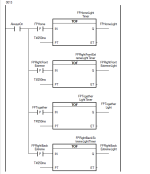
If I increase those windows, will I risk lowering my accuracy in position tracking? Say for example, I make my "FPTogether" zone, which is at 180 degrees be a range of +/-15 instead of +/-10 degrees. And on the -|P|- pulse of this range being true I indicate something on my HMI. I would like to have my zone output at a pretty consistent position. As I continue to widen my ranges, am I creating more variability/less precision on when the zone output is displayed?
 
Is your PLC catches pulses from encoder?

It's 1440 pulses per revolution. Am I right?

What technically "puls" is?

When you run the encoder with a 12 VDC motor at 80 rpm it's

1400 pulses per * 80 rpm = 115200 pulses per minute.

Am I right?

So 60 sec / 115200 pulses per minute = 0.00052 sec per pulse.


What your PLC scan time?

Is rotation speed constant?
  • Yes, my plc catches pulses from encoder
  • its a 360 PPR encoder, so 1440 counts per rev
  • I have my program as a 1 ms task class
  • In my bench system, yes speed is constant. In my application there will be slight dips in speed.
 
If I increase those windows, will I risk lowering my accuracy in position tracking?
Opening the window would be if the PLC has an issue responding to the present setup. If it sees it then ok.
If I open the window I would add more (not +/-15, but +30/-0) and add a OneShot check after it so it doesn't happen twice and happens at 180 or greater.
 
Some updates: I replaced my motor to a worm gear motor for my bench system and tested at 34 rpm. Much more accurate results, but still occasional skips, or completely unresponsive for a few seconds.


If I increase those windows, will I risk lowering my accuracy in position tracking? Say for example, I make my "FPTogether" zone, which is at 180 degrees be a range of +/-15 instead of +/-10 degrees. And on the -|P|- pulse of this range being true I indicate something on my HMI. I would like to have my zone output at a pretty consistent position. As I continue to widen my ranges, am I creating more variability/less precision on when the zone output is displayed?
You can always have different windows for displaying status vs running actual logic
 
Opening the window would be if the PLC has an issue responding to the present setup. If it sees it then ok.
If I open the window I would add more (not +/-15, but +30/-0) and add a OneShot check after it so it doesn't happen twice and happens at 180 or greater.
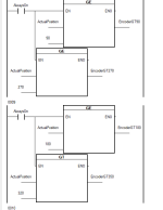
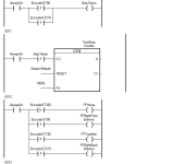
Since the UI lights lagged/missed some zones, I made a counter for "zone count" to ensure that there were 4 counts per rev to verify each zone is caught, which is working well. I also verified that the zone counter is always 2 x step counter. I will occasionally see my counter increment faster for a moment then increment at a normal rate again. My concern is ensuring the accuracy of when the zone is detected. Slight angle changes correspond to noticeably different locations within the step cycle. I can do a visual check on the angle each time the zone counter increments, but I'm sure there are others way I can my this more precisely in my logic.

1710780255202.png 1710780276024.png


1710780311922.png
 

Attachments

  • 1710780296031.png
    1710780296031.png
    29 KB · Views: 1
In addition to this, I have to figure out how to go about determining the live RPM. One method I know to do this would be:
  1. find pulses per second (PPS)
  2. PPS x 60 = pulses per minute (PPM)
  3. PPM / PPR= RPM
    1. (encoder PPR = 360 pulses per rev
However, I am unsure the best way to step #1 with my given module. Or is there a better way to do this? Once I get RPM I will use it to find live speed and distance travelled for various other metrics. Advice is greatly appreciated! :)
 
Unless PPM is exactly a constant doing that calculation would result in a bouncing value that could be unreadable.

Every 5 seconds check the encoder count, after 2 seconds check the count again. Make sure the value did not reset and B is GRT A.

Subtract A from B for counts per 2 seconds and do math on that.
 
Will my counter incrementation I mentioned previously cause an issue with this approach (quoted below)? For example, if the last encoder counter check was at ~32700 and the next check 2 sec later was at ~ -32500 or something similar after it negates.
The way I was doing this is by taken total counts (EncoderPosition) and dividing by 720 (counts in half rev for one step). But when I do this I count up to 46, then this negates to -46 and counts back down and repeats. I believe this is because the module I am using for this sensor has max count of 32767, so it increments up to this value, negates, and counts back to 0.

I have my step counter working fine with this current logic above, but do I need to adjust the counter to get my live rpm? If so I was planning to do the following:
  1. On Z pulse reset EncoderPosition to 0 (so Encoder position is always 0-1440 counts)
    1. I can use the counts to determine position in degrees (EncoderPosition/4 = 0-360 degrees)
  2. Create variable TotalCounter. On Z pulse, add 1440 to TotalCounter.
  3. EncoderPosition + TotalCounter = LiveCounter (running total counter until reset)
Is something like this necessary for the suggested approach? It sounds like LiveCounter would be the count I would need to use for live RPM because I currently do not have a running total due to my 12 bit counter module.
 
  • if new >= old, then delta <= new - old
  • if new < old, then delta <= (new - (-32768)) - (old + (-32768))
then work with the delta i.e. add delta to a running total that you assume rolls over at 1440 i.e. subtract 1440 from running total when running total exceeds 1439. Then angle (= running total ÷ 4) will always be in the range [0.0:360.0).

This assumes it never runs backwards, but that can be handled too with some more modeling assumptions.

Or, if you detect the Z pulse, then subtract 1440 from the EncoderPosition (don't reset to 0; you will miss pulses then)./
 
Wait a minute, is EncoderPosition the counter accumulator that is counting incoming pulses, so it accumulates 1440 every rotation, and it rolls over from 32767 to -32768? I.e. the EncoderPosition rollover has nothing to do with the rotation rollover (Z pulse)?
 
I took some time away from the project, but I am back.
Wait a minute, is EncoderPosition the counter accumulator that is counting incoming pulses, so it accumulates 1440 every rotation, and it rolls over from 32767 to -32768? I.e. the EncoderPosition rollover has nothing to do with the rotation rollover (Z pulse)?
Yes, the first statement is correct. It is probably poorly named right now, but EncoderPosition is the variable for the "live" encoder counter, it is continuously incrementing up until it reaches 32767, and then rolls over to its inverse and repeats that cycle. I have another variable, EncoderPositionLatch that simply holds the EncoderPosition, and it only updates on the z signal.

What can I do in order to get more precision on the zone detection? The device will not exceed ~38-40 rpm. Would something like this work?
  1. On Z pulse reset EncoderPosition to 0 (so Encoder position is always 0-1440 counts)
    1. I can use the counts to determine position in degrees (EncoderPosition/4 = 0-360 degrees)
  2. Create variable TotalCounter. On Z pulse, add 1440 to TotalCounter.
  3. EncoderPosition + TotalCounter = LiveCounter (running total counter until reset
 
What can I do in order to get more precision on the zone detection? The device will not exceed ~38-40 rpm. Would something like this work?

> 1. On Z pulse reset EncoderPosition to 0 (so Encoder position is always 0-1440 counts)

I don't think that will work, because on the scan cycle when the Z pulse occurs, the count will be greater than 1440 e.g. 1441 so 1 pulse beyond "top dead center," so if you reset the 1441 to 0 then you lose that pulse, and that kind of error accumulates over time. Even if you subtract 1440 from 1441 and write a 1 to the accumulator, by the time you do the subtraction and write it might have advanced to 1442, so you can still lose pulses.
 
That makes sense. Is there a better way to do my accumulation to prevent "losing" those pulses? With the odd rolling-over-counter logic I have now, I can get total steps taken, position readout (0-360 degrees), and the zone detection working to a degree. But improving the clarity of my encoder position in order to make the "zone catching" more precise is my end goal.
 
That makes sense. Is there a better way to do my accumulation to prevent "losing" those pulses? With the odd rolling-over-counter logic I have now, I can get total steps taken, position readout (0-360 degrees), and the zone detection working to a degree. But improving the clarity of my encoder position in order to make the "zone catching" more precise is my end goal.
on each scan cycle,
  • subtract* the current_accumulator value from the previous_accumulatorvalue,
    • the difference is the change_in_pulses for the current scan cycle
  • move the current_accumulator value to the previous_accumulator tag (for the next scan cycle)
  • add the change_in_pulses value to the current_position_in_pulses tag
  • If the current_position_in_pulses value is greater than 1439, then subtract 1440
  • If the current_position_in_pulses value is less than 1439, then add 1440
  • current_position_in_pulses ÷ 4 = angle_in_degrees.
There needs to be some way to assign an initial current_position_in_pulses when the system starts up.

* the subtraction may overflow or underflow (a 16-bit signed INT) if the change from the previous_accumulator value to the current_accumulator value goes through the -32768:+32767 wraparound, so you need a way to deal with that, but it only takes a little bit twiddling when rollover is detected. I assume you can do that, but if you want the details I could provide them.
 

Similar Topics

Sorry in advance for the long post, but this requires a little back story. I work in a facility with a couple hundred VFDs Most are in a web...
Replies
14
Views
220
I have an application using an incremental encoder and then I convert it to degree (0-360) using calculation program. For a while, the calculation...
Replies
8
Views
289
Hi everyone, This is my first time posting, so please forgive any omissions or mistakes. I am attempting to control the velocity of a stepper...
Replies
18
Views
1,017
Dears, i am trying to change the series of encoder from A to B, but the program do not has this option (Rslogix5000, 20.06 the old encoder was...
Replies
2
Views
211
Hi all, I am implementing an incremental encoder sensor (ABZ) to replace the existing "manual" encoder wheel I have in my device. This is a 360...
Replies
0
Views
168
Back
Top Bottom