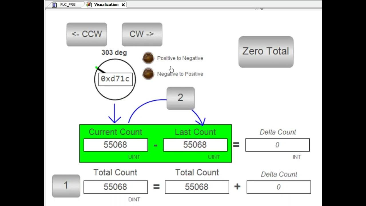
Encoder Revolution Counter

I think the best way is to always reference your total accumulator and do math on that value. So, if you use a Modulo math function on the accumulator and 1440, the remainder will always be a fraction of that. This way, you will never lose an accumulated value. You can also use these same remainder function to determine the precise angle each cycle in a much simpler fashion I believe. As for the RPM, you can compute the delta in accumulator each PLC scan and compare the value. Hopefully you have access to the last scan time of the PLC as well, and you can take the delta and scan time to determine the Rate Per Scan. Multiple this out to your RPM and average over a few scans (say 1 second or more). I think that should work.
 
... So, if you use a Modulo math function on the accumulator and 1440, the remainder will always be a fraction of that. ...

This is the other approach, but requires a [modulo 1440] offset, initialized to 0, to be
  • to be incremented by 736* at every +32767 => -32768 rollover, and reduced modulo 1440,
  • to be incremented by 704* at every -32768 => +32767 rollunder, and reduced modulo 1440.
  • and added to the [-32768:+32767] accumulator value, and the sum reduced modulo 1440 for the final value.
This assumes the modulo instruction always returns a positive value, even if the input operand is negative.

* I might have those reversed; it's simple to test.
 
on each scan cycle,
  • subtract* the current_accumulator value from the previous_accumulatorvalue,
    • the difference is the change_in_pulses for the current scan cycle
  • move the current_accumulator value to the previous_accumulator tag (for the next scan cycle)
  • add the change_in_pulses value to the current_position_in_pulses tag
  • If the current_position_in_pulses value is greater than 1439, then subtract 1440
  • If the current_position_in_pulses value is less than 1439, then add 1440
  • current_position_in_pulses ÷ 4 = angle_in_degrees.
There needs to be some way to assign an initial current_position_in_pulses when the system starts up.

* the subtraction may overflow or underflow (a 16-bit signed INT) if the change from the previous_accumulator value to the current_accumulator value goes through the -32768:+32767 wraparound, so you need a way to deal with that, but it only takes a little bit twiddling when rollover is detected. I assume you can do that, but if you want the details I could provide them.
I agree with everything you said here, except I would do this for rollover detection and accumulation. I think the way to detect the rollover is to look for when the current - previous value goes negative, then you would want to trigger a counter. This counter should have an output whose value is a multiple of the total expected range of the data type, here, 65536 (an INT). Then, you would add the current accumulator to the rollover_count * accumulator_range to get current_accumulator (the actual total pulses).

The way to determine the current_position_in_pulses would likely need to be a calibration routine that occurs between power cycles or before an actual test. This can be achieved, if I am following the details correctly, by taking steps until you get a rollover. Once you detect this rollover, you know exactly where you are at.
 
this thing is going 40rpm max and 1440 pulses per revolution, so there are just under 60000pulses per minute, assuming a scan time of 1-10ms, there can be no more than 1-10 pulses of change per scan cycle, and certainly no more than 766. So this should do t'job:

MOV current_accumulator change_in_pulses
GRT change_in_pulses 32000 LES previous_accumulator -32000 OTL change_in_pulses.15 OTU previous_accumulator.15
GRT previous_accumulator 32000 LES change_in_pulses -32000 OTU change_in_pulses.15 OTL previous_accumulator.15
SUB change_in_pulses previous_accumulator change_in_pulses
MOV current_accumulator previous_accumulator

The code to handle initialization will be much more complex than that, whatever method you choose.
 
The way to determine the current_position_in_pulses would likely need to be a calibration routine that occurs between power cycles or before an actual test. This can be achieved, if I am following the details correctly, by taking steps until you get a rollover. Once you detect this rollover, you know exactly where you are at.
So the more I thought about this, the more I realized that likely isn't helping if you really want to keep the actual position in line with the program. The rollover of the current - previous will help you get realigned to ensure you are on track (or you can simply just 0 the program out at the start of each test), but if you really need it to be aligned with the physical world, then you need some method to determine when the motor itself hits some specific position. In some encoders, this is done by removing a tooth and generating a longer gap then normal. It generates a sine wave that has a gap at some known position every revolution, then you know the starting position. In digital form, this might look like 101010010101001010100... those extra zero's are the 0 position of the shaft, and when programmed appropriately, you can detect this and pick it up. Now, that's a bit harder as you would need to be able to identify this. If you had a way to wire into your counter card some signal that did this externally, then you can probably pick this up and use it to effectively "reset" the accumulator on the counter card, and then expect you to monitor and reset this bit. To do that, obviously your scan time needs to be much faster than each revolution so you don't miss a rollover event, but achievable potentially. If necessary, you could possibly use an Event to interrupt your normal PLC scan to process this specific thing, but I'm not sure what the PLC capabilities are or if this is even needed (likely only if the scan time is not fast enough).

One thing to keep in mind... we are always looking at the fastest rate we would ever expect, but you should also look at the slowest rate. For the accumulator, this isn't a problem, but if you are doing any RPM calculation as we suggested and averaging it, if you have 0 change in the accumulator between scans, you will get a 0 RPM value. Do this enough, and you could see less than ideal rates or 0 depending on how much you sample and how you do it. Just be aware of some of the shortcomings of this method, and you will be fine. How you choose to do this will greatly depend on how reliable this will be. One way to do it is to create another accumulator that is reset each second, and the value right before you reset converted to RPM's would likely get you what you want. you could then average that over a longer time if you want, but should get you what you desire.
 
Removing a tooth would yield a pattern pf 10101000101010001010100, not 101010010101001010100.

At 40RPM and 1440 pulses per revolution, this encoder is generating pulses too fast for the PLC scan cycle to detect individual pulses, so OP is using a high-speed counter (HSC), assuming that HSC does not miss any pulses, and using the HSC accumulator to track the position of the encoder. So finding a missing tooth for top dead center is not going to work unless the speed is kept below 20RPM or so.

Taking the HSC accumulator value modulo 1440 works until the accumulator rolls over, either from +32767 to -32768 for forward rollover with otherwise advancing counts, or from -32768 to +32767 for reverse rollover with otherwise decreasing counts. The problem is that +32767 modulo 1440 is 1087, and -32768 modulo 1440 is 352; so when the HSC accumulator advances from +32767 to -32768, the naive modulo calculation motor position changes from 1087 (= +32767 modulo 1440), not to 1088 (= (1087 + 1) modulo 1440), but rather to 352 (= -32768 modulo 1440) i.e. 736 less than it needs to be. The simple solution, as provided by my code in post #32, is to increment a "rollover offset" by 736 at each rollover going forward and to decrement that offset by 704 (= 1440 - 736) at each roll"under" going backward, to reduce the incremented or decremented rollover offset modulo 1440. Then on each read of the HSC accumulator value (-32768:+32767), sum that rollover offset with the HSC accumulator value modulo 1440, and to final reduce that sum (HSC accumulator plus rollover offset) modulo 1440, which will then always represent the encoder counts of the current encoder position forward and relative to the initial 0 position, no matter how many times the HSC accumulator rolls over or under.

The only trick is to find that initial 0. One way would be to have an initializing pushbutton: rotate the device slowly; on any scan cycle when the Z signal has a rising edge while that pushbutton is held in, clear the both HSC accumulator value and the rollover offset to 0. As long as the device and encoder are rotating slowly enough, this will yield an initial 0° position to within a small number HSC counts. For example, at 4RPM, one pulse cycle is 10ms+, so assuming the Z pulse profile matches the A pulse at top dead center, the Z-high duration will be at least 10ms, which should be long enough for most PLCs to catch, for an initialization accuracy of at most one count (¼°).
 
Removing a tooth would yield a pattern pf 10101000101010001010100, not 101010010101001010100.
Encoders now are optical with a through beam sensor detecting the fine marks on a glass plate.

Also, the OP wants to reset when the mechanics make one step and that could be a few hundred revolutions of the motor and encoder.
 
I am working with an incremental encoder (ABZ signals, 360 ppr (so 1440 counts per rev)) to replace the existing "manual" encoder wheel I have in my device. This is for a medical device with 2 footplates that cycle through steps via a linkage system, so 1 revolution = 1 stride = 2 steps (1 right and 1 left step)). My goal is to get total steps taken.

Encoders now are optical with a through beam sensor detecting the fine marks on a glass plate.

I know the A and Z signals are separate for OP. I was just saying that when other installation's Z signals are provided as suggested by "removing a tooth," then the pattern would not be 1010101010100101010.

Also, the OP wants to reset when the mechanics make one step and that could be a few hundred revolutions of the motor and encoder.

One encoder revolution is one step; see quote above from post #1. Post #18 says PLC scan cycle is 1ms, which is still not fast enough for the max expected speed of 40RPM = 57,600ppm ≈ 1kHz, so the 1ms-task (sample) rate of 1kHz (60,000sample/min) is barely half of the necessary Nyquist rate of of 115,200sample/min ≈ 2kHz.
 
Thank you for the suggestions. One clarifying question before I ask other questions on the suggestions.

These are all of the IO mapping options I have with this ABZ counter module. Currently the iCounter variable is the encoder accumulator that is incrementing to +32767, rolling over to -32767, then incrementing to +32767, and repeating this cycle. My initial idea was that on the positive trigger of the Z signal, I will turn on qResetCount and increment a separate counter, previous_counter by 1440. Then iCounter +previous_counter = total_accumulation. But will this method create that "loss in a count" discussed in Post #28 ?
1712941773720.png
 
Last edited:
But will this method create that "loss in a count" discussed in Post #28 ?

that would be my concern, yes; at 1ms for the interrupt scan it's on the edge and might not be an issue, but I would not trust a system with that kind "might."

All of the suggestions are basically trying to get around this one issue by allowing the HSC to simple increment its accumulator by 1 for each pulse and compensating for the resulting issues with software, so it's not ideal but it should work. The root "problem" is that the counter accumulation runs essentially independently with respect to the PLC, which is good because it means the PLC does not have to detect every signal edge, but it also bad because anytime you have that level of asynchronicity, all bets are off. For example, you say the task is running on a 1ms interrupt, but do you know how often the HSC updates the image of the counter state in PLC memory?

I don't know if it is available in this PLC in this HSC module, but some HSC modules (e.g. 2080-MOT-HSC for the Micro800 PLCs) have a configurable feature to reset the accumulator value to 0 when the value reaches some preset. It seems like that would be a pretty common thing to do, so that feature be what I would look for: then you could simply set the preset to 1440 and forget about the rest of this circus (modulo, offset, roll-over/-under, etc.) because that feature handles it for you.
 
Long ago OkiePC made a good post. I gave it a thumbs up.
All of this has been solved long ago.
This thread has wasted enough time. The OP made a mistake by using an encoder with 360 lines or 1440 counts per revolution.
Always use an encoder that provides a power of 2 counts/rev. This way the math can be done by shifting, adding and subtracting.
It is easy to computer the number of turns by shifting left. One can and with a mask to get the fraction within a turn.
If your use a 16 bit counter then you don't need to worry about overflow or under flow when subtracting the old counts from the new counts.
The difference should be added to a 32 bit accumulator if necessary. If the high speed counter provides only 12 bits then shift the bits left 4 times to make it look like a 16 counter with poor resolution. All this has been worked out many decades ago.
There is no hope unless a high speed counter card is used and it should use the A,B and Z inputs. When stopped it is possible for the encoder to vibrate and add lots of counts. The B phase will take care of that by adding and subtracting counts as the encoder vibrates back and forth.
High speed counter cards usually sample at 8 times the max encoder counts. The encoder inputs go into a series of D flip flops and 3 D flip flops but be high or low to result in high or low. This is the de-glitching. The PLC alone can't/don't do this. Never reset the the high speed counter!. See #28. Enable the z pulse to latch the z input and count when homing. Base everything as an offset of the latch z counter. This way you don't lose counts due to resetting the high speed counter.

The RMC encoder inputs does over sampling. It has 3 latches, one for the Z, and the end and retract limits. We never reset the accumulator. This way you don't have the problem noted above in #28. Position are a offset from the latched counts in the Z register or the extend or retract register.

I always asked the customer how many counts per second they expected. If the counts per second was not greater than half the RMC's
8M counts per second, then I told the customer to buy an encoder with more counts per revolution and make sure the counts per revolution is a power of 2.
I /we/our customers have found that an coder with 8192 or 16384 counts per rev doesn't code any or much more than lower count encoder. The only problem with these high count encoders it that you can't feed them directly into a PLC or many counter cards because the counts are too high.
 
Hi all,

I am working on a project that needs to detect when a user is putting in effort into the system (this is a robotic gait trainer that functions similar to a elliptical). I am looking at the RPM of the motor to determine this. When the user inputs effort, an increase in RPM can momentarily be seen while effort is being exerted, and the HMI indicates that effort was made live.

Due to the system's linkage design, the RPM fluctuates through a range based on the users speed and step length (e.g. The motor is set to run at 25 rpm, but live readout of the RPM will be 22-27. When effort is exerted, you can see the the range shift to be 25-30).

Right now, my logic will scan motor for a 5 seconds, pull what the max RPM value is, and use that at the reference against the live read out, so in my example, if the RPM exceeds 27, the user has put in effort). However I want to try to make it more sensitive. For the RPM values that overlap in the NoEffort and Effort RPM ranges, is there anyway to differentiate between the effort vs. non-effort? I attached a rough sketch of what my HMI trend lines look like for each scenario. Thank you!
@afm, is the current thread taking place within the framework of solving the above issue?

In 85 posts, you didn’t bother to formulate exactly what information the end user needs.

Have you heard the term “design” - formulation of a problem, analysis of difficulties and solutions, selection of methods and their preliminary verification?

Although you may not believe it, I will give you the most valuable advice of all the advice given you on this forum:
Stop wasting YOUR time on solving “issues” (in fact, solving your “issues” by forum participants) that in no way bring you closer to achieving your final goal.

It is impossible to solve a problem that is not formulated.
I gave MaxK a thumbs up but I don't agree with the last statement. There is the right way to use encoders and the wrong way.
I do agree that the OP's are rarely providing the application they are trying to do and why. It is rare that something similar hasn't been done before.
There are too many threads that take too long if ever to be resolved because the OP doesn't provide the necessary information.
 
Hi all,

This is the same system you are referring to @MaxK, yes, all of my projects are based off of this system which is why there is overlap with this thread and previous threads. I have very little to no guidance on much of my work, and many of the suggestions are not approaches I have tried before. So forgive me for being slow to catch on to much of this, I am slowly learning. Let me try to explain more clearly.

@afm, is the current thread taking place within the framework of solving the above issue?

In 85 posts, you didn’t bother to formulate exactly what information the end user needs.

Have you heard the term “design” - formulation of a problem, analysis of difficulties and solutions, selection of methods and their preliminary verification?

Although you may not believe it, I will give you the most valuable advice of all the advice given you on this forum:
Stop wasting YOUR time on solving “issues” (in fact, solving your “issues” by forum participants) that in no way bring you closer to achieving your final goal.

It is impossible to solve a problem that is not formulated.
The thread you are referring to is a separate project that is somewhat on pause, so I am not considering this right now. In the future I plan to go back to address some of the shortcomings I have faced in that project due to the lack of positional data I have currently. Which is where this project comes in...

Again, this is a medical device similar to an elliptical, so there are 2 footplates. The end goal of this project is to achieve "position tracking", i.e. tell me where users are within a step (footplates together, right foot forward, left foot forward, etc.). The current system uses a "manual" encoder wheel system: a metal wheel with 8 pulses (i.e. 8 equally spaced cut outs) with an inductive sensor to count steps (every 4 pulses = 1 step, 8 pulses = 1 rev = 2 steps) and to calculate speed and distance. Obviously this system gives us is very limited information. We want better resolution to know which foot is taking a step (right or left) and where it is within that gait cycle. So my first task if to replace the existing metrics I have with the old system (get steps, speed, distance) and the next task is to get the new metrics (position tracking/zones).

This thread has wasted enough time. The OP made a mistake by using an encoder with 360 lines or 1440 counts per revolution.
Always use an encoder that provides a power of 2 counts/rev. This way the math can be done by shifting, adding and subtracting.
Hardware is not finalized, I can switch to a 256, 512, 1024, or whichever ppr that will make it easier, any advice on knowing which to select that will be suitable for my 12 bit counter?
 

Similar Topics

Sorry in advance for the long post, but this requires a little back story. I work in a facility with a couple hundred VFDs Most are in a web...
Replies
14
Views
242
I have an application using an incremental encoder and then I convert it to degree (0-360) using calculation program. For a while, the calculation...
Replies
8
Views
328
Hi everyone, This is my first time posting, so please forgive any omissions or mistakes. I am attempting to control the velocity of a stepper...
Replies
18
Views
1,045
Dears, i am trying to change the series of encoder from A to B, but the program do not has this option (Rslogix5000, 20.06 the old encoder was...
Replies
2
Views
216
Hi all, I am implementing an incremental encoder sensor (ABZ) to replace the existing "manual" encoder wheel I have in my device. This is a 360...
Replies
0
Views
170
Back
Top Bottom