GX Developer Lead/Lag logic

tobytommas65

Member
Join Date
Dec 2020
Location
Canada
Posts
1
I am a novice at ladder logic programming but I needed a lead/lag function for two pumps that I am controlling. I bought a cheap FX1N(C) board from Alibaba and our shop had a old copy of the freeware GX developer lying around.

Anyways the logic below is what I came up with. Seems to work.
 
Welcome to the forum.


Are you honestly trolling* for comments and/or suggestions?


* non-"internet trolling" i.e. non-malicious trolling
 
First of all you do not need M0 just use X0 in place of M0 also no need to use M3, there are special relays M8000 > these have various functions like Always true always false, true for first scan etc.
M8000 is always true while PLC is in run
M8001 is false
M8002 is on for first scan of PLC.
So instead of M3 just use M8000 to move zero into the D register.
Just noticed that this will not work at all as when X0 (M0) goes off then it will cause Y0 or Y1 to go false and as this is before the add function that requires Y0 or Y1 to be on it will be false so never adds or subtracts the value.
In saying that if it does work on yours then I suspect that the FX1N you may have could be a clone and not a real Mitsubishi there are a lot about and the I/O may work differently, on a true FX1 this logic will not work and to prove it I just tried it, you need to move the two add/subtract lines before the outputs i.e. move them between lines 8 & 10.
In actual fact this logic is not duty but really a flip/flop i.e. when X0 goes on first time it runs pump 1 then as it is toggled it switches between pump 1 & pump 2.
 
You should read the manual there are lots of functions that can reduce your code as this example, it alternates between the two pumps using the ALT function the code only takes 3 lines including the outputs.

ALT.png
 
I concur with what parky says:

  • the code, as written, will not work on most PLCs, for the reason parky states;
  • there are only two states, so you can use a bit, instead of an integer that has the value 0 or 1*, to implement lead-lag behavior.
Also, that ALT instruction parky used, which I assume toggles M0, is much simpler than five instructions arranged as a flip-flop to do the same thing, as I would have suggested. The only functional difference is I would have used a falling edge to trigger the ALT.
 
Last edited:
The ALT instruction uses a rising pulse to change state, however, it does not have to be a pulse as just using X0 will still work so when X0 goes true it turns on M0 and when it goes true again it turns M0 off so if you use a falling pulse then M0 will not turn on first true of X0 i.e. on PLC first run pressing X0 (assume button) would start motor 2 not 1, you could change the N/O, N/C contacts but what is the point in using a falling edge.
 
... what is the point in using a falling edge.


I had assumed ALT executes when the rung feeding it was true, not when the X0 in the previous instruction becomes 1, and I also did not know the ALT executes only on the rising edge of the rung i.e. false-to-true transition of rung.


But whoops: my mistake was that I did not pay attention to parky's code that had NO (--] [--) on M0 for Y000, and NC (--]/[--) on M0 for Y001.


I assumed parky had NC (--]/[--) for Y000, and NO for Y001 i.e. similar to the OPs program ([= K0 D100] for Y000, and [= K1 D100] for Y001). If it was that way (NC on M0 for Y000), then M0 would not toggle until each pump turned off, and Pump 1 would come on initially (assuming the initial value in M0 was 0). So what I would have accomplished by inverting the X0 contact, parky accomplished by "switching" the M0 contact types. One effect (slight advantage?) of triggering the ALT when X0 becomes 0 is that the order of the rungs does not matter, because the pump-start logic is decoupled from the toggle-M0 logic.


In practice it probably does not matter of course, we are only talking about which pump starts first after the PLC program starts.


And since the ALT is triggered by the rung rising edge, parky can use a NO on X0 and I can use a NC on X0.
 
Last edited:
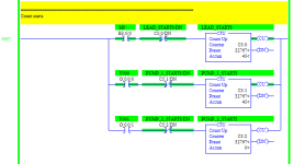
I ported the OP's program to a MicroLogix 1100, and confirm that it does not run Pump 2 as written.


Here is an image of the money shot from functionally equivalent code, which also counts the numbers of

  • lead pump starts
  • Pump 1 starts (same as lead pump starts)
  • Pump 2 starts (always 0)
leadlag_running.png


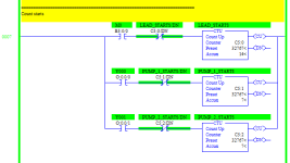
And here is an image of the money shot of the same code with the fix suggested by @parky i.e. put lead-pump-change rungs before pump-start rungs.

  • lead pump starts
  • Pump 1 starts (~half of lead pump starts)
  • Pump 2 starts (~other half of lead pump starts)
leadlag_fixed_running.png


The code is also attached in a .ZIP: _fixed means fixed code; _running means data saved while running; there are PDFs of the running cases.
 
You are correct, it is possible for contact bounce this would have to be more than one scan but with small scan times this certainly can happen. But in all the years I have been programming (and the amount of time using OSR's never really had a problem), then again it would also make sense to delay the start of a pump after a stop so as not to overdo the number of starts per hour, you will always get the numpty who will continuously keep pressing the button.
 
You are correct, it is possible for contact bounce this would have to be more than one scan but with small scan times this certainly can happen. But in all the years I have been programming (and the amount of time using OSR's never really had a problem), then again it would also make sense to delay the start of a pump after a stop so as not to overdo the number of starts per hour, you will always get the numpty who will continuously keep pressing the button.

Parky I have to laugh (Numpty) I hope drbitboy gets the reference! Lmho

Ray
 
Parky I have to laugh (Numpty) I hope drbitboy gets the reference! Lmho

Ray


I spent a couple of years working at Fawley Refinery four decades ago. I'm not a native speaker (two countries separated by a common language 'n'all ;)), but I've heard the term.


Also, I have a compliment for the OP. This seems a decent effort on OP's first program as well as on their first thread on this forum: OP stated the problem clearly; OP tried to do it themself; OP showed their efforts; OP included comments in the documentation. Okay, maybe they didn't know all the tricks, but their basic concept was pretty close.


Finally, OP not provided any feedback; I hope they found this helpful.
 
TL;DR

@parky's solution is the right answer for the OP:

xxx.png

Whether to add a debounce and/or an input map depends on the hardware.

However, someone searching for lead/lag in the future and finding this thread, but having a PLC that does not have the ALT instruction, cannot use that solution as written. The alternative is to use a flip-flop circuit for the first rung above [XIC X000 ALT M0]:
Code:
   X000               
----] [---------------------[OSR                     ]---
                            [Storage       X000_store]
                            [Output  X000_rising_edge]

     X000_Rising_Edge    M0              M0
--+------] [------------]/[------+------( )---
  |                              |
  | X000_Rising_Edge    M0       |
  +------] [------------] [------+
N.B. A-B ladder used for the OSR [one-shot rising] instruction; some other OEMs do not have the --]^[-- instruction, as in rung 0 of @parky's example.

N.B. X000_Rising_Edge is only true for one scan i.e. in A-B parlance it is the output of a one-shot.

EvenLonger;DR

Laying in bed thinking about this (yeah, I gotta get a life ;)), I wondered if the Y000/Y001 states could be a proxy for the storage bit of the one-shot determination, and came up with this hot mess:
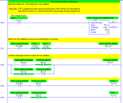
yyy.png

Which is at least cleaner than the original, even hotter mess:
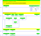
zzz.png

:ROFLMAO:
 
Last edited:
your over thinking the flipflop here is a simple one without the slug & outputs.
It's funny but nobody has mentioned it lead/lag ? I think the title is a little out a lead/lag, this implies that the lead pump runs, if it cannot meet the demand then the second pump kicks in so both pumps can run together not one or the other, to me this is duty/standby so in a multiple pump system then there is a lead pump & the other (s) lag, the pump that leads can be swapped to a lag so you have both lead/lag & duty.
for those AB guys the PLS is OSR.

Flipflop1.png
 

Similar Topics

I'm trying to verify a project with a PLC. The Transfer Setup menu item is grayed out and every time I click Verify with PLC, I get an error...
Replies
1
Views
58
Well, I've decided to start a new project, and like all projects, it has already gone horribly wrong. I purchased a PLC device (supposedly a...
Replies
2
Views
113
Does anybody have any samples of how to "Create and Use" UDT's in CCW Developer Edition? (I am using v22) I can't find any information from...
Replies
3
Views
318
I'm trying to manually convert a Beijer E200 HMI project onto to a new Mitsubishi GOT gs2107-wtbd. The PLC is a very old A-series AS1CPU and is...
Replies
1
Views
384
Hi One of the PLC's that I maintain/update is a Mitsubishi Q-Series, probably installed about 10 years ago. At the moment, ALL the wires from...
Replies
13
Views
1,174
Back
Top Bottom