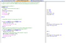
This works when I compiled there were a number of errors
1. the variables Real_xx would not compile because real is a reserved word (no idea if you have them as local or global variables but I suggest you need them as globals
The IF / Else etc produced another compiler error as it was incorrect.
Why are you setting the output to full scale on first scan ? what is the point, if you have something connected to it i.e an analogue sensor it will overwrite it.
If not it will never get to overscale ?
Attachments
Last edited: