GX WORKS2 Rising/falling edge detection in ST.

mikeromeo

Member
Join Date
Mar 2024
Location
UK
Posts
10
I have a FX3U clone that I am failing to get a simple Structured Text example working on and would really appreciate some help. I created a simple ladder project that works exactly as expected, but have failed to get an equivalent ST program working. The program is very simple:
1. Sets DAC output 0 to full scale immediately after start up by checking for a rising edge on special register M8002 (I'm using this output as a 10v reference for a potentiometer).
2. On the rising edge of the 10ms clock register M8011 it samples analog input channel 1 (connected to potentiometer) and stores the value in D0.
3. On the falling edge of M8011, the value in D0 is written to analog output 1.
4. On each scan cycle the Y0 relay is set if the value in D0 is higher than half scale, otherwise cleared.

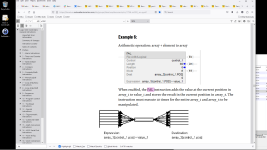
This is the ST program. The initialisation of DAC channel 0 works correctly, but the rising/falling edge detection of M8011 simply doesn't work, those code blocks are never entered. I have tried using LDP/LDF instructions (since this works on M8002) and also PLS/PLF instructions. Help!

Code:
(* Check for start up condition *)
IF LDP(TRUE, M8002) THEN   
    (* Set DAC channel 0 to full scale output.  THIS WORKS! *)
    D0 := HFFF;
    WR3A(TRUE, K0, K0, D0);
END_IF;

(* Check for clock rising edge *)
(* IF LDP(TRUE, M8011) THEN    *)
PLS(M8011, M0);
IF M0 THEN
    (* Read ADC channel 1. NEVER GETS HERE! *)
    RD3A(TRUE, K0, K1, D1);
END_IF;

(* Check for clock falling edge *)
(* IF LDF(TRUE, M8011) THEN    *)
PLF(M8011, M1);
IF M1 THEN
    (* Write ADC result to DAC channel 1. NEVER GETS HERE! *)
    WR3A(TRUE, K0, K1, D1);
END_IF;

(* Set/Clear Y0 output depending on ADC channel 1 value *)
Y0 := (WORD_TO_INT(D1) > H7FF);
 

Attachments

  • analog_ld.png
    analog_ld.png
    58.6 KB · Views: 16
Seems a little weird using the IF statementsThe way to use the pulse in ST is like this I don't have a clone at the moment so cannot try the analogues but this is the way to use the pulse types, also I assume you are using possibly GXW2 or is it GXDeveloper, my version of GXDeveloper does not have ST it is greyed out so did this in GXworks2 in this IDE you do not need to use the K constant but you do in GXDev. below is shown how you do not need the IF statements as the RD3A function in ST instead of using the TRUE statement just put the pulse bit in there.
PLS( M8011 ,M3);
ADD_E(M3,1,D1,D1); (* just for clarity & testing I'm using the ADD function *)
PLF(M8013,M6);
ADD_E(M6,2,D3,D3);

RD3A( M6 , K0 , K1 , D10 ); (* This is what I would expect your code to look like *)
EDIT: oops just noticed you are using GXW2 so no need for the K suffix.
 
(* Check for start up condition *)
(*No need for LDP, M8002 is already initial pulse)
IF M8002 THEN
(* Set DAC channel 0 to full scale output. THIS WORKS! *)
D0 := HFFF;
WR3A(TRUE, K0, K0, D0);
END_IF;

(* Check for clock rising edge *)
(* IF LDP(TRUE, M8011) THEN *)
(* I would try with M8012, as 10 ms is too fast for Chinese clone *)
PLS(M8012, M0);
SET(M0, M1)
(* Read ADC channel 1. NEVER GETS HERE! *)
RD3A(M1, K0, K1, D1);
SET(M1, M2)
RST(M1, M1)
(* Write ADC result to DAC channel 1. NEVER GETS HERE! *)
WR3A(M2, K0, K1, D1);
RST(M2,M2)

(* Set/Clear Y0 output depending on ADC channel 1 value *)
Y0 := (WORD_TO_INT(D1) > H7FF);

PS: I did not try program, just directly wrote it according to your code
 
Why are you not using LDP and LDF instead of PLS and PLSF?

Also, the LDP on M8002 (First-pass bit) makes no sense; M8002 is always only a one-shot.

Anyway, this should work; I also swapped back the D0 and D1 to match the ladder example.

Code:
(* Buffer instantaneous value of 100Hz (10ms) clock *)
M0 := M8011;

(* Check for start up condition *)
IF M8002 THEN

    (* Ensure first-pass scan cycle cannot detect a rising edge *)
    M1 := M0;

    (* Set DAC channel 0 to full scale output.  THIS WORKS! *)
    D1 := HFFF;
    WR3A(TRUE, K0, K0, D1);

END_IF;

(* Check for clock rising edge *)
IF M0 AND NOT M1 THEN
    (* Read ADC channel 0. *)
    RD3A(TRUE, K0, K1, D0);

END_IF;

(* Check for clock falling edge *)
IF M1 AND NOT M0 THEN

    (* Write ADC result to DAC channel 0. *)
    WR3A(TRUE, K0, K1, D0);

    (* Set/Clear Y0 output depending on ADC channel 0 value *)
    Y0 := (WORD_TO_INT(D0) > H7FF);

END_IF;

(* Store current value of clock signal for edge detection on next scan cycle *)
M1 := M0;
 
Here is how you embed certain functions like ANDP into another function
Instead of
PLS(M8011, M0);
IF M0 THEN
(* Read ADC channel 1. NEVER GETS HERE! *)
RD3A(TRUE, K0, K1, D1);
END_IF;
This simplifies it any function that uses the result
RD3A( ANDP(TRUE,M8011) , 0, 1 ,D100 );

Here is some code that should work it is your code modified but not added the reset of Y0

(* Check for start up condition *)
D0 := HFFF;
WR3A(M8002, 0, 0, D0);
(* Read ADC channel 1. *)
RD3A(ANDP(TRUE,M0), 0, 1, D1);
(* Check for clock falling edge *)
(* Write ADC result to DAC channel 1. *)
WR3A(ANDF(TRUE,M8011), 0, 1, D1);

See how simple it becomes by embedding the ANDP & ANDF functions in the analog read/write
Not tried this as do not have a clone but it compiles & I tested it on an FX3U but substituted move functions in place of the analog read/write as I do not have any analog cards or built in ones
 
Thank you all for your help, what a great place this is!

The use of D1 and D0 is swapped between the ladder and ST versions of that code, I think.

Yes I noticed this a while after posting so the programs are not exactly equivalent, though I don't believe this should change the operation.

Seems a little weird using the IF statements

There will ultimately be more code within the IF blocks, including some math operations on the ADC values.

(* Check for start up condition *)
(*No need for LDP, M8002 is already initial pulse)
IF M8002 THEN
(* Set DAC channel 0 to full scale output. THIS WORKS! *)
D0 := HFFF;
WR3A(TRUE, K0, K0, D0);
END_IF;

(* Check for clock rising edge *)
(* IF LDP(TRUE, M8011) THEN *)
(* I would try with M8012, as 10 ms is too fast for Chinese clone *)
PLS(M8012, M0);
SET(M0, M1)
(* Read ADC channel 1. NEVER GETS HERE! *)
RD3A(M1, K0, K1, D1);
SET(M1, M2)
RST(M1, M1)
(* Write ADC result to DAC channel 1. NEVER GETS HERE! *)
WR3A(M2, K0, K1, D1);
RST(M2,M2)

(* Set/Clear Y0 output depending on ADC channel 1 value *)
Y0 := (WORD_TO_INT(D1) > H7FF);

PS: I did not try program, just directly wrote it according to your code

Thanks for the hint on M8002, it's obvious now you've said it that this register is only active for a single scan cycle so I don't need to look for an edge. I have tried with M8012, this at least makes debugging easier I can see the values changing in the GX Works monitor, but it did not make the program work. M8011 also works fine with the ladder version.

Why are you not using LDP and LDF instead of PLS and PLSF?

Also, the LDP on M8002 (First-pass bit) makes no sense; M8002 is always only a one-shot.

Anyway, this should work; I also swapped back the D0 and D1 to match the ladder example.
I originally used LDP/LDF (they are commented out in my OP) but when I couldn't get them working I tried PLS/PLF instead. I have tried your suggestion for edge detection but it still doesn't work, and the monitor output doesn't make a lot of sense. In the short video below, you can see that M1 is not being updated and even if I manually change it's value I don't see D0 being updated with the analog input value, and the analog output 0 never gets set either (analog output 1 does get set, as before). This is using the M8013 one second clock to enable reliable monitoring.


This is the instruction list that is generated:
Code:
0    LD M8013
1    OUT M0
2    LDI M8002
3    CJ P2051
6    LD M0
7    OUT M1
8    LD M8000
9    MOV H0FFF D1
14    LD M8000
15    WR3A K0 K0 D1
22    P2051
24    LD M0
25    ANI M1
26    OUT M7679
29    LDI M7679
32    CJ P2052
35    LD M8000
36    RD3A K0 K1 D0
43    P2052
45    LD M1
46    ANI M0
47    OUT M7679
50    LDI M7679
53    CJ P2053
56    LD M8000
57    WR3A K0 K1 D0
64    LD> D0 H7FF
69    OUT Y000
70    P2053
72    LD M0
73    OUT M1
 
This line two statements:
2 LDI M8002 and
3 CJ P2051

makes PLC app always jump to P2051 (line 22) always except in initial scan.
 
Here is the code I posted no cJ jumps simple as IL

0 LD M8000
1 MOV H0FFF D0
6 LD M8002
7 WR3A K0 K0 D0
14 LD M8000
15 ANDP M0
17 OUT M7679
20 LD M7679
23 RD3A K0 K1 D1
30 LD M8000
31 ANDF M8011
33 OUT M7679
36 LD M7679
39 WR3A K0 K1 D1
 
I originally used LDP/LDF (they are commented out in my OP) but when I couldn't get them working I tried PLS/PLF instead. I have tried your suggestion for edge detection but it still doesn't work, and the monitor output doesn't make a lot of sense. In the short video below, you can see that M1 is not being updated and even if I manually change it's value I don't see D0 being updated with the analog input value, and the analog output 0 never gets set either (analog output 1 does get set, as before). This is using the M8013 one second clock to enable reliable monitoring.

I don't know why, but I suspect that that code is not being evaluated, because the last statement never changes the value of M1 to be the same as M0.

Add a statement

Code:
real_all := real_all +1.0;

after the M1 := M0; statement.

Then add a statement real_rising := real_rising + 1.0; inside the IF M1 AND NOT M0 THEN-END_IF clause, and add another real_falling := real_falling + 1.0; inside the IF M0 AND NOT M1 THEN-END_IF clause, where real_all, real_rising, and real_falling, are all REAL data types. If my suspicion is correct, those REALs will never increment.
 

Attachments

  • 1712244050419.png
    1712244050419.png
    224.1 KB · Views: 2
Why read the analogs on a timebase why not read them every scan (I know Mitsi show this but not actually required, again the iff statement not required no need to put other maths code in there if you are using a pulse trigger just use that in the maths after all the if statement is doing the same thing except it's jumping round things waste of resources.
Attached is a program that runs a PI temperature control loop on a clone just borrowed a mates clone & it works, note: the only thing where I use a time generated pulse is in the PI loop not the analogues.
I originally wrote this in FBD but my mate wanted simple ladder on seperate rungs hence lots of M of the same address rather than putting many branches off one bit.
 

Attachments

  • PID In clone.pdf
    83 KB · Views: 2
Why read the analogs on a timebase why not read them every scan (I know Mitsi show this but not actually required, again the iff statement not required no need to put other maths code in there if you are using a pulse trigger just use that in the maths after all the if statement is doing the same thing except it's jumping round things waste of resources.
Attached is a program that runs a PI temperature control loop on a clone just borrowed a mates clone & it works, note: the only thing where I use a time generated pulse is in the PI loop not the analogues.
I originally wrote this in FBD but my mate wanted simple ladder on seperate rungs hence lots of M of the same address rather than putting many branches off one bit.

Again this is a proof of concept, I have a working ladder example and I'd like to create the equivalent in ST. I don't want to put a bunch of workarounds in without understanding why it doesn't work as that's a sure fire path of having it break again when I add more code.

This line two statements:
2 LDI M8002 and
3 CJ P2051

makes PLC app always jump to P2051 (line 22) always except in initial scan.
That is the desired behaviour, the code in lines 6-15 should only get executed once after start up. Ironically this is the only part of the code that actually works!

I don't know why, but I suspect that that code is not being evaluated, because the last statement never changes the value of M1 to be the same as M0.

Add a statement

Code:
real_all := real_all +1.0;

after the M1 := M0; statement.

Then add a statement real_rising := real_rising + 1.0; inside the IF M1 AND NOT M0 THEN-END_IF clause, and add another real_falling := real_falling + 1.0; inside the IF M0 AND NOT M1 THEN-END_IF clause, where real_all, real_rising, and real_falling, are all REAL data types. If my suspicion is correct, those REALs will never increment.

I've done this and as per your (and my) suspicions none of the blocks after "IF M8002 THEN" are being executed, even if I manually toggle M1 through the watch window. Out of interest is there a reason to use the REAL type for debug code like this? Typically in C/C++ I always use a simple integer type for this kind of debugging, but as you can tell I am very new to PLCs.

I had a very slight success by putting the rising/falling edge code into an ELSE block:

Code:
(* Buffer 1 second clock *)
M0 := M8013;

(* Check for start up condition *)
IF M8002 THEN
    (* Ensure first pass scan cycle cannot detect a leading edge *)
    M1 := M0;
    (* Set DAC channel 0 to full scale output. *)
    D1 := HFFF;
    WR3A(TRUE, K0, K0, D1);
    real_all := 0.0;
    real_rise := 0.0;
    real_fall:= 0.0;
   
ELSE

    (* Read ADC channel 1 on rising edge of clock *)
    IF M0 AND NOT M1 THEN
        RD3A(TRUE, K0, K1, D0);
        real_rise := real_rise + 1.0;
    END_IF;
       
    (* Write ADC result to DAC channel 1 on falling edge of clock *)
    IF  M1 AND NOT M0 THEN
        WR3A(TRUE , K0, K1, D0);
        (* Set/Clear Y0 output depending on ADC channel 1 value *)
        Y0 := (WORD_TO_INT(D0) > H7FF);
        real_fall := real_fall + 1.0;
    END_IF;
   
    (* Store current value of clock for edge detection on next scan cycle *)
    M1 := M0;
    real_all := real_all + 1.0;
END_IF;

This code does read the analog input into D0 and I see 'real_rise' increment but this happens at the scan rate, not with a one second peroid. Nothing after this block gets executed. Following this I moved the falling edge blocks into it's own ESLIF block, and duplicated the M1 := M0; statement for each. Sadly this stopped it all working again (except start up block).

Code:
(* Buffer 1 second clock *)
M0 := M8013;

(* Check for start up condition *)
IF M8002 THEN
    (* Ensure first pass scan cycle cannot detect a leading edge *)
    M1 := M0;
    (* Set DAC channel 0 to full scale output. *)
    D1 := HFFF;
    WR3A(TRUE, K0, K0, D1);
    real_all := 0.0;
    real_rise := 0.0;
    real_fall:= 0.0;
   
ELSE

    (* Read ADC channel 1 on rising edge of clock *)
    IF M0 AND NOT M1 THEN
        RD3A(TRUE, K0, K1, D0);
        real_rise := real_rise + 1.0;

        (* Store current value of clock for edge detection on next scan cycle *)
        M1 := M0;
        real_all := real_all + 1.0;
       
    (* Write ADC result to DAC channel 1 on falling edge of clock *)
    ELSIF  M1 AND NOT M0 THEN
        WR3A(TRUE , K0, K1, D0);
        (* Set/Clear Y0 output depending on ADC channel 1 value *)
        Y0 := (WORD_TO_INT(D0) > H7FF);
        real_fall := real_fall + 1.0;
       
        (* Store current value of clock for edge detection on next scan cycle *)
        M1 := M0;
        real_all := real_all + 1.0;      
    END_IF;

END_IF;

It feel like it may be time to bin the clone and invest in a real PLC. A lower cost device that supporta ST, has analog inputs and with free or low cost software would be ideal but the choice is bewidering.
 
I've done this and as per your (and my) suspicions none of the blocks after "IF M8002 THEN" are being executed, even if I manually toggle M1 through the watch window. Out of interest is there a reason to use the REAL type for debug code like this? Typically in C/C++ I always use a simple integer type for this kind of debugging, but as you can tell I am very new to PLCs.
The problem is somewhere else and not in the details of that code. The problem is that that entire section/routine of code is not being called and executed/evaluated, from the main program or otherwise, by the PLC.

If those statements are not executed/evaluated by the PLC, then their logic cannot change anything.

I chose REALs so there would be no problem with overflow: the counters will stop incrementing at around 16M (224), which is fine because they are only a diagnostic, but that not cause a CPU fault, which happens when incrementing integers on some PLCs.
 

Similar Topics

I'm starting learning ladder programming. I bought the FX3U kit + coolmay HMI from aliexpress. I'm doing basic testing and uploading codes. I...
Replies
57
Views
3,956
Hello to all, is my first post on the forum, I searched everywhere, but I could not find an answer to this problem; I am quite experienced in...
Replies
13
Views
989
hello, I'm trying to set up communications between two Mitsubishi L series PLCs using the built in Ethernet port. All of the information I can...
Replies
6
Views
1,899
Hello Friends, I am trying to index M Bits, however GX Works2 is not allowing it with following message. https://ibb.co/zPcqj6M...
Replies
3
Views
1,391
Hello all. Am new with Mitsubishi plc programming,I need two upload program from FX3S-20MT CPU,so I ask about the the cable used to interface...
Replies
8
Views
2,184
Back
Top Bottom