Having trouble coding this, any help would be appreciated.

plcnoop

Member
Join Date
Jun 2019
Location
US
Posts
15
The program seems and sounded simple enough to me, but I'm having trouble with it anyway. I'll give a quick rundown of what the system should do.


It should control a valve and has an open and closed position. It is normally closed. Opening/closing works by energizing and de-energizing a coil on a relay. When energized, it opens, when de-energized it closes.


The valve status is determined by a float switch that is normally closed. When the float is closed (in it's default position) the coil should be de-energized.


Now when the float opens it should start a 12hour timer. After that timer it should energize the coil (tell the valve to open).


When the float goes back down and closes (returns to it's default position) it should start a 31 hour timer after which it closes the valve.


So float goes up, 12 hour timer starts and valve opens, it stays open for X amount of time (until float goes back down) after float goes down valve stays open for 31 hours and then closes.


I guess the part I'm having a problem with is the de-generalization of a coil. I know how to energize them in ladder logic, but de-energizing them is a head scratcher to me (I'm very new to this so be gentle).


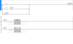
This is what I have right now. The main problem is that with the current logic the valve will immediately de-energize, instead of waiting the 36 hours. I imagine I need to branch something off of the first run to keep it open while the timer in TON_2 completes. I'm not sure how to accomplish that.


Any other suggestions or simpler ways to accomplish what I'm trying to do are appreciated. And remember, I'm pretty new to all of this so keeping it simple and talking to me like I'm an idiot is welcome lol.

Thank you guys for having such a helpful community.


QMpUEzC.png
 
Hi
Everyone started somewhere


Your relay is just a switch to open the valve. The relay is ON when your output is ON, OFF when your output is OFF so use your output to be ON (Energise) or OFF (De-eneregise).


SO create conditions in your code using the float status to latch timers to give you your 2 timer requirments. Look up 'seal-in' circuits


Your homework is vague , real world would have high level switch at least to stop a fill


Haha, believe it or not, this is a real world application for a pond basin. These are the actual sequence of operations they gave me and the only input is a float switch that's either up or down.


I'll see what I can find in regards to "seal-in" circuits.
 
Yep you need a TON for the opening and a TOFF for the closing. I would use a Set/Reset instruction.
You can also do it with two TON's but takes a little more logic, you might need a status or flag bit.
 
You can do this several different ways but here's how I'd go about it. You can use two TON's, one for the 12 hours and the other for the 31 hours. Using your ladder, I replaced the output with a single bit (a BOOL labeled "OPEN_CLOSE") that is then tied to a physical output (VALVE_CONTROL). When the first timer is done the bit is latched energizing the output. When the second timer is done the bit unlatched de-energizing the output.
Having said all of that, I think you will need more ladder than that to deal with situations where the valve needs to be open or closed inside/outside of the timer's control but that's not for me to decide.

VALVE 02.jpg
 
I'm not sure which PLC software you are using, but it would be easier to make TON_2 a TOFF timer instead.


I went ahead and did this and it seems to be functioning perfectly with the push buttons I have here at the house to simulate the float/manual open.


You can do this several different ways but here's how I'd go about it. You can use two TON's, one for the 12 hours and the other for the 31 hours. Using your ladder, I replaced the output with a single bit (a BOOL labeled "OPEN_CLOSE") that is then tied to a physical output (VALVE_CONTROL). When the first timer is done the bit is latched energizing the output. When the second timer is done the bit unlatched de-energizing the output.
Having said all of that, I think you will need more ladder than that to deal with situations where the valve needs to be open or closed inside/outside of the timer's control but that's not for me to decide.


This made more sense to me initially but (again I'm a complete noob) I had no idea how to get the outputs you were using. The open/close bits.
 
This made more sense to me initially but (again I'm a complete noob) I had no idea how to get the outputs you were using. The open/close bits.

In CCW, you can create variables in several formats including DINT's (Double Integers), INT's (Integers) and BOOL's (bits). The outputs on rungs 1 and 2 are a Bool type variable I created called “OPEN_CLOSE”. On Rung 1 it is controlled by a “Latch” output command and on Rung 2 it is controlled by an “Unlatch” command so when Rung 1 is true the bit “OPEN_CLOSE” is latched I.E. locked in an energized state and when Rung 2 is true it is unlatched de-energizing it. Because it’s a variable (not a physical output) it can then be used as the input on Rung 3 to control the output (which is a physical output) labeled “VALVE_CONTROL”.
The reason I use a bit to control a physical output is I find it easier to manipulate the bit in ladder logic than the physical output.
In CCW’s help section, do a search for “Variables” and read up on them. It should make more sense after you do, and it is something you will certainly need to understand moving forward with PLC programming.
P.S. A “Variable” in CCW is a “Tag” in Logix programming software
 
Hi, I am posting 4 pictures of some options of what you can do.


You will need some more details for the project, as I can see so many possibilities for the "simple" control that could have been overlooked (I say "simple" because defining the nitty-gritty details sometimes are more complicated than one may think). For instance:


1. What should happen if the float turns on and starts the 12 hour timer, but then shuts off as the timer is running (before the valve opens)? Should the timer just reset and next time the float goes high start the 12 hour timer all over again? Should the timer pause, remember where it left off, and resume if the float turns on again? Should it run the 12 hour timer with no regard for the state of the float after the timer starts? Conversely, how should the valve close logic operate (same three questions)?


2. If the PLC power is lost, what should the valve state be after reboot? Should it switch back to where it was when power was lost? Should it revert to closed and start the 12 hour timer all over again if it powered on with the float in the high position? The valve will shut off when power is lost (since you seem to have only a single output for the valve - it doesn't have explicit open and close solenoids or actuators per your description and code sample).


3. Do the times need to be adjustable without modifying the code (variables accessible with an interface screen (HMI), for instance)?


Option 1 depicts the simplest control with a neat TONOFF instruction that keeps the code very clean. It will reset the timer if the float changes state during the time period. That is, if the float turns off during the 12 hour period, it will reset the on-timer (and the valve will stay closed). If the float turns on during the 31 hour period, it will reset the off-timer (and the valve will stay opened). If the PLC power is lost, everything will go back to default (valve closed and require a full 12 hours of steady float high input status to open again).


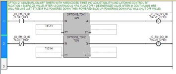
Option 2 uses two timers and latches the output using SET and RESET commands. This will work exactly as Option 1, except when the PLC reboots after a power loss, the valve will go back to the state it was in (if it was opened, it will open, and if it was closed, it will stay closed). Again, the timers will reset if the float changes state during the on and off time periods.


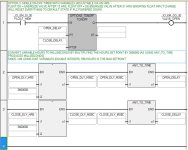
Option 3 replicates Option 1, but adds the ability to link the timers to an HMI. Unless you do fancy programming, the HMI will pass a number to the PLC, so the two additional lines of code convert the hour set points entered on the HMI into milliseconds that the ANY_TO_TIME instructions will then pass to the TONOFF instruction. I wrote it using DINT data types, so 596 hours is the max hour set point that can be entered ((((2147483647/1000)/60)/60) = 596). Allowing a bigger number will cause a negative time value to be calculated and screw everything up.


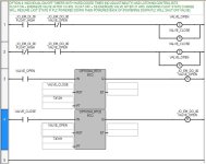
Option 4 replicates Option 2, except that it will ignore the float status once the float calls for the valve to open or close. That is, once the timer starts, it is running to completion. To accomplish this neatly, I added two helper bits that monitor both the float input status and valve output status. I also used retentive timers, so if power is lost, the time resumes where it left off. I needed to use two helper bits to reset the timers, otherwise it would lock up. Only a true state at the reset input of the timers will reset them, so I couldn't just use one bit to do so. I also noticed that I used "VALVE_OPEN" for both the output alias and one of the helper bits - they should be named differently for the sake of reducing confusion (like naming the output alias to "VALVE_OPEN_SOL").


Depending on the "nitty-gritty" details of the project, you may find taking pieces from each of these options will get you where you need.

OPTION 1.JPG OPTION 2.JPG OPTION 3.JPG OPTION 4.JPG
 
Last edited:

Similar Topics

Hey guys, I worked on this all night last night and all afternoon today. I have a SLC5/04 that I am trying to make a msg read from a PLC 5/20. I...
Replies
5
Views
2,228
So long story short I'm frustrated at work because I can't get my timer to actually time in the FB's. I have been using the SB4 blocks in my FB...
Replies
12
Views
3,111
Hi Everyone! I'm new to PLC and ladder diagram and i was hoping if any of you could help me explain what do these applied instructions mean. I...
Replies
6
Views
2,281
The ATv 31's and 312's worked great. sans so move and the documentation. Why did they have to discontinue them? The 320's are not performing...
Replies
2
Views
1,806
Hello, I am on a automotive line right now (4 segments) and we have a barcode reader at the beginning of each segment at the elevators. The...
Replies
4
Views
2,289
Back
Top Bottom