HF Scientific CLX Modbus RTU

OkiePC

Lifetime Supporting Member
Join Date
Mar 2005
Location
ENE of Nowhere Oklahoma
Posts
11,794
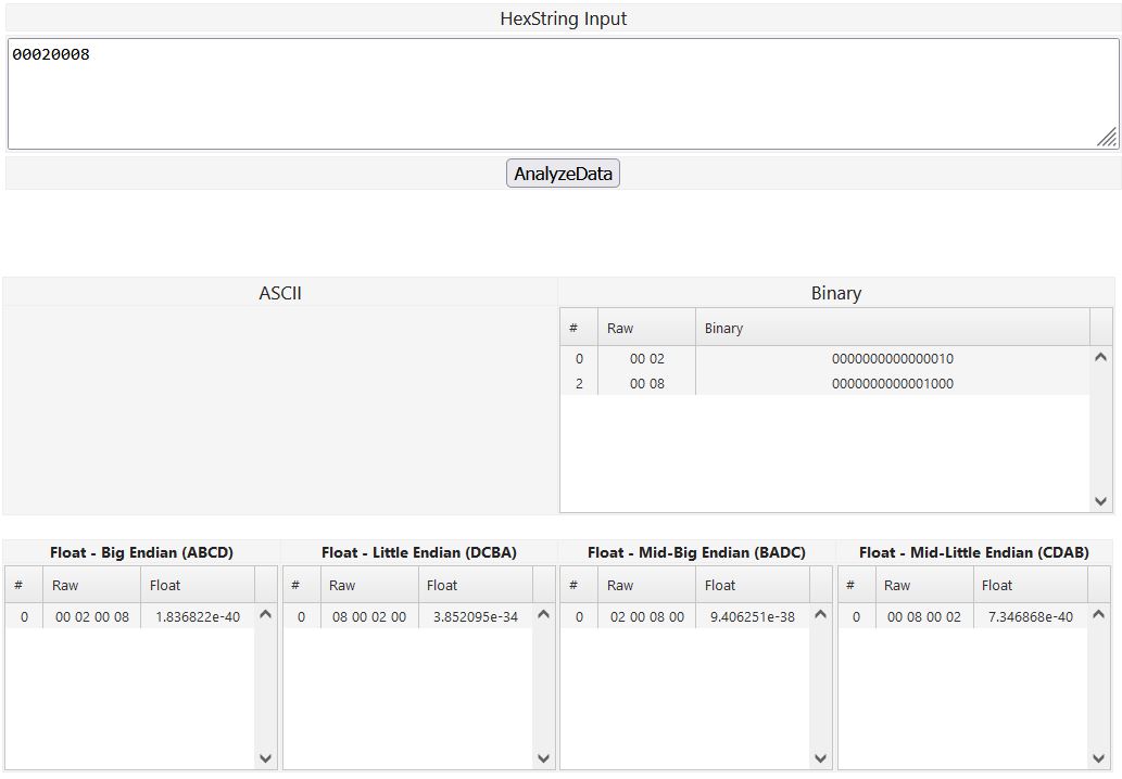
Working with a CLX Cat # 20040 RS485 port Modbus RTU and I am not getting the expected data from for the sensor reading. I expected an IEEE754 float, but with the display showing 1.28ppm, I get a value of "2" from input register 30001, and "8" from 30002. Reading all 16 Input Registers no pair of them appear to be the right bit pattern for "1.28" as a 32 bit float.

Have any of you used the Modbus feature of that Chlorine analyzer? I have a Chloramine Analyzer right next to it that is working fine with Modbus RTU and I am low on analog inputs for that PLC so I thought I would do Modbus RTU and also collect all the other status info from it.

I tried to submit a tech support request online with Watts (who now owns HF) but their page is apparently broken because it will not let me submit.

if I can't figure it out I may have to add another input card and do it old school with 4 to 20mA and skip all the status information.
 
Last edited:
I don't have direct advice, like experience with that model of chlorine analyzer.

Can you post the actual Modbus data, ideally as a hex dump but also as the PLC registers associated with the 3xxxx addresses.

What make/model of PLC and interface are you using ?

Is the Modbus polling completing successfully with good checksums ?

It's a Click Plus PLC. I am on a different job today but should be back out there tomorrow or Monday and I can get a snapshot of the data coming into the Click. One of my complaints about A/D PLCs is that you don't get all the data in the processor for offline viewing or I could post it now.

I am not sure if I can capture the serial data stream through the Click software, but I do have an RS422/485 to USB converter for my laptop that I might be able to use in conjunction with some capture software if you have any recommendations. I don't think it is a Click problem because the same PLC is reading another Modbus RTU device flawlessly.

I am pretty sure it is completing with a good checksum since I do have the optional Exception Response Error Code populated with a PLC address in the Receive instructions and in the past when I have made a programming error, that response code does seem to work.
 
Are you sure which registers are you reading?

  • Input registers
    • Modbus Addresses 30001, 30002
    • PDU Addresses 00000, 00001
    • Modbus Function code 0x04
  • Holding registers
    • Modbus Addresses 40001, 40002
    • PDU Addresses 0000, 0001
    • Modbus Function code 0x03
?

2 and 8 look more like Holding Registers' values.

Are you aware the whole off-by-one issue common to Modbus communications?
 
I am not sure if I can capture the serial data stream through the Click software, but I do have an RS422/485 to USB converter for my laptop that I might be able to use in conjunction with some capture software if you have any recommendations.


Do. This.

Post the bytes streams, for both Master and Slave, in hex.

Let me know what OS you are running if you cannot find a program to do that. Linux would be easiest; WSL in a VM should also work.
 
I read that user manual and came to the same conclusions you did that the Float datatypes are handled like it says: mantissa and exponent packed into two Modbus 16-bit registers. That's a totally normal, common, as-close-to-standard-as-it-gets way to handle Floats in Modbus.

1.28 would be represented as a Float as 1.2799999713897705078125, which would be in hex as 0x3fa3d70a.

But you have hex values that show you a "2" and an "8", but not a "1".

That is close to maybe being a Binary Coded Decimal packing, but it doesn't make sense for them to be spread out over two 16-bit words, instead of in two adjacent 4-bit nibbles. And of course the user manual doesn't mention BCD anywhere.

The Modbus Holding Register 40001 also confuses me: I don't understand why you need a "number of decimal places" to do floating-point values.

That would be more appropriate for integers with implied decimal places, but then you would see 1.28 represented as 128 decimal = 0x80 hex.

I agree that intercepting the Modbus data might be the necessary next step. I look forward to seeing it !
 
Yes, 0x00020008 makes no sense.

0x00020008-makes-no-sense.jpg
 
I am reading all the Input Registers and the Holding Registers. I haven't bothered with the digital inputs or the coils.

The Decimal places register is just for the LCD display. You can read or write that register to set the number of decimal places shown on the display.

I should be able to get back out there today and dig into this again. I ordered some 120ohm resistors since I was getting some errors on the Receive command only for that device, I'd expect the termination won't fix it, but I have learned to never say never in this line of work.
 
This capturing requires one of our (ICC's) gateways, such as the Mirius.
http://www.iccdesigns.com/protocol-gateways/66-mirius.html


If you only have a USB to RS-485 adapter, you can try using this command-line software to take a Wireshark capture:
https://github.com/j123b567/SerialPCAP


It uses the same USER_DLT value of 147 by default as the ICC gateways, so this video would apply:
https://www.youtube.com/watch?v=YtudbhexPv8&list=PLsV5cTr-4yCnFGDxCHQ4KkMUp_gie1qCm&index=7


Note that you may need to increase the GAP value so the packets are interpreted properly and not split up.
 
I typed this out as I made these trials.

Okay, I added the termination resistors and now I am consistently getting errors with my Receive message.

This program is pretty long and to rule out the risk of something dumb stepping on my data I made a new file with only a single receive instruction for all 21 Input Registers.

Same thing, but it shows exception error 3 'illegal data address in request', so I dropped it back to 2 words. Now there no errors, valid IEEE794 data in those 2 registers. I just put a simple repeating timer to drive it every 2 seconds and for 30 seconds it was perfect. The numbers all jive and no errors.

Great, so it must be me (the full program) or (unlikely) my other PLC and HMI on the Ethernet network. I bumped it back up to 20 addresses and still good. I am thinking the document is wrong and that the last Input Register data type is a single integer and not a long integer.

The device is okay, my program or some other thing is interfering.

So I go back to my long program where the messages for this and 2 other devices are all in a subroutine and change the order of the messages around, change the length to 20 and ... errors... No error code, just errors.

So now I remember a long time ago with some Click Ethernet messages, in order to get my logic to execute properly I had to switch the scan mode to fixed. I also change the IP address in case the other ethernet devces are erroneously overwriting things.

Still errors, "0" for exception response.

Scrutinizing my logic, I add a check for the "Port 3 Ready" system flag to the message sequence logic.

No help.

So I disable the message sequence control subroutine and manually manipulate the steps. Success! Good data (20 words, not 21). So I put everything back to normal (IP address, scan style) and slow my polling way down and all is well.

The bottom line is that there are 20 Input Registers, not 21 (at least in my new device) and that if you overwhelm the serial port on the CLX you might get bogus data out of it.

I have a value I can adjust for "Message Interval" that puts a pause in milliseconds between each message. A value of 500 (half a second between messages) is too fast. 600 is fine. At 500ms between polls (even though there are six steps and only one other on this RS485 channel) the Receive Instruction errors with a zero for exception response, which if I had to guess meant a bad checksum?

I appreciate the tips on the port sniffer too. If I hadn't forgotten to grab my table from yesterday's jobsite and it was less than 95 degrees in this little building, I might camp out for a few more hours and drill deeper.

Thanks to all contributors.
 
Last edited:

Similar Topics

Respected Members rather Mentors, I am cracking my head to sort out an issue regarding RSView32 Trend object. In that trend, assigned flow...
Replies
2
Views
1,781
I'm using a 2080-LCD with a Micro 810 to display analog values and display it on the LCD. However, some values display in scientific notation ex...
Replies
3
Views
2,057
Hello, I was donated a working Pacific Scientific SC750 servo drive and servo motor from my workplace. I am in the process of modifying my hobby...
Replies
10
Views
7,164
Hi there, I have some real values I want to display in a report. ON a graphic display the value appears as 109652. On the report is appears as...
Replies
1
Views
1,518
Hi guys, I am trying to print a basic report in Citect (7.1 +SP2) containing production stats but all my integer data is being output in...
Replies
0
Views
1,468
Back
Top Bottom