drbitboy
Lifetime Supporting Member
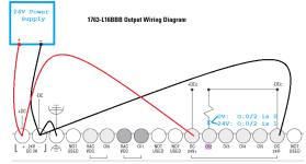
Are the red and black wires in the image below the right way to drive a 0V or 24V discrete output signal from a O:0.0/2 of a MicroLogix 1100?
Also, do I have the right behavior described for the voltage at the blue x?
If yes to both, then I am pretty sure this is a sourcing output. Do I have that right?
I realize the design of the load will also need to limit the current, but I am more interested in getting the wiring right for now. Also, I realize that 0V and 24V are nominal, and the actual signals might not be exactly those levels because O:0/2 uses a FET.
The base diagram is from the ML1100 Installation Manual here.
I understand Ohm's law reasonably well, but I am definitely weak when it comes to terminology and jargon of DC. After a while I finally realized (I hope) that "DC 24V-" is an alternate expression for "COMmon" i.e. the low side of a 24V range, and is not the same as "DC -24V" i.e. a voltage 24V below a ground level voltage.
There is an old thread about a similar task here. The OP in that thread mentioned connecting the COM and the GND, but I am guessing it would also work if the DC 24V- IN and the O/2-O/5 "DC 24-" (DCc) were isolated from the ground (⏚).
Sorry for the basic questions, but I could not find anything that laid it out like that: the base diagram does not show +DC IN and -DC IN connected to +DCc and -DCc, respectively. That is probably obvious to everyone, and they are not connected in the base diagram because the designer may want to supply an external voltage source to +DCc and -DCc, but it was not obvious to me.
Thanks.


