Looking for a strategy to decelerate a hydraulic cylinder

Yep - one empty slot is available. I also have 5 outputs and and 8 inputs available on the i/o cards installed.

I forgot to ask what the voltage and current rating of the outputs and inputs are.

Also I cannot tell from your posts, do you already have a solenoid valve that shunts the flow control? If you do, can you purchase another? also what is it's voltage and current rating.

Looking at the documentation for the Gemini 1000 it looks like it will accept just about any encoder. What we need to know is what the output of the encoder is (Voltage).

While on the subject of the encoder and Gemini, I'm presuming that the reset input is being used. Is the reset from the encoder (Z pulse) or from a limit switch?

Do you have Direct Soft (programming software)?

Do you have the existing program? If you do not, then we will have to reverse engineer the program.

Do you have cables for the optimate and programming software?
 
Anyone with experience feel free to share info on one versus the other... I also have an optimate display / keypad to add to the mix that I picked up with an entire spare matching plc a while back. Again - very green on PLCs, so I figured I would start by setting up the second PLC as a testbed to read the encoder and integrate the HMI without messing up the working one in the bender right now.
I have no experience on CTRIO versus CTRINT, but I have used Optimate operator panels. They are okay if you need limited inputs. I think if you have 10 numbers to input, you would be better off in the long run to use a larger graphic panel with room to show all 10 angle inputs at the same time. This will allow an operator to double check his inputs. If you use an Optimate, there are different models, but for the 600 series there are only 4 lines on the display. You can set up a menu so that you might get 10 number inputs, but you will not be able to see all of them at the same time. One of the C-more Touch Panels might be a better fit. Also check the Red Lion brand operator panels.
 
The inputs are all 24volt dc off the base of he Plc. The outputs are 115v relays - not sure of the amperage.

There is not a solenoid directly acting at the flow control. I'll post an old schematic hat is pretty close to what's in there now.

I do have directsoft 5, andhave recently started playing with it some. Have the cable for it, and I've pulled the current program out. I have downloaded he optimate software, but have not gotten the cable for it yet. I know a cmore woul be better, an ill probably go that route after I prove I can figure out all the programming.

I would hate to hav to buy a big enough vfd for this thing! I'm not sure how well I would work as there are multiple cylinders applying loads during the bend. Interesting thought, though.

I'm not actually resetting the redlion counter. Zero on the bend arm is zero, an it repeats day in, day out. I counts up to the setpoint, then back down to zero as the arm swing back. I hav gone months without resetting the zero.
 
I added a quadrature encoder to the bend spindle and a red lion controls gemini 1000 counter. That let me digitally set the bend angle (and read it) to about a 1/4 degree accuracy (using a 360 div encoder in 4x mode). I then simply used the relay in the counter to replace the old limit switch.
I'm not actually resetting the redlion counter. Zero on the bend arm is zero, an it repeats day in, day out. I counts up to the setpoint, then back down to zero as the arm swing back. I have gone months without resetting the zero.
So the Red Lion counter has a relay output that stops the bending. Does it have any other type of output that would tell the PLC what count it is on? If you had the counter ported to your PLC, then you could use that to control where the bender stopped, substituting a PLC output for the counter relay output. Then you could let the PLC calcuate some other Count to stop on, instead of the setpoint (Setpoint minus some adjustment factor).
 
The inputs are all 24volt dc off the base of he Plc. The outputs are 115v relays - not sure of the amperage.

Do these outputs power the existing solenoid valves directly or is there something in between?

Is there a 24 volt power supply?

I do have directsoft 5, andhave recently started playing with it some. Have the cable for it, and I've pulled the current program out.

This implies that you do not have the programing with the original author's comments and descriptions. If you do not have the original we will need a I/O list. The I/O list is a list of inputs (names) and their relationship with each input. The same goes for the outputs.

An example would be:
X0 Cycle push button
X1 start hydraulics push button
X2 stop hydraulics push button
X3 home position limitswitch

Y0 Follower shoe retract
Y1 Follower shoe extend
Y2 5in bend cyl w/large shaft extend
Y3 5in bend cyl w/large shaft retract

You may have to do this by manually by tracing the wires. There is also a way to use Direct Soft to help. Use the programing you previously uploaded from the PLC. Click on "PLC" at the top of the window, a dropdown list will appear, click on connect. Click on "Debug" at the top of the window, a dropdown list will appear, click on "all status on". Click on the "data view" icon, if you cannot find the "data view" icon, check under "view", "data view". At this point you should be online and a data view window should be open. One of the columns in the data view will be labeled "status" we are now interested in the other column. Place the cursor in this column and click on the first row, type in X0, hit enter, arrow up, then hit cntrl-enter this will populate the data view with X0, X1, X2 ect. for each cntrl-enter do this for the number of inputs on the PLC. Now when you push a button or move a limit switch you can see the status of the input change. So you should be able to see which button changes which input. After the inputs are done see if you can do the outputs.

If you are up to it you can enter the names of the inputs and outputs to their respective addresses. I think you can put the cursor in the row and click, then hit cntrl-d to bring up the descriptions editor. At this point you can name the address hit enter then cntrl-l to get you back to the data view. After you have done this you save your work find the files on your hard drive there should be between 5 to 10 with the same name but different file types .LDA, .LDO ect zip them up and post, we can then help with the rest of the descriptions.

I'm not actually resetting the redlion counter. Zero on the bend arm is zero, an it repeats day in, day out. I counts up to the setpoint, then back down to zero as the arm swing back. I hav gone months without resetting the zero.

I have attached a portion of the Gemini pdf. What I'm wanting to know is what is connected to the input I circled.
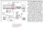
gemini.jpg
 
Last edited:
Milldrone, there is nothing connected to the Reset terminal.
I'm not actually resetting the redlion counter.

I have downloaded he optimate software, but have not gotten the cable for it yet.
TublarFab, Which Optimate model do you have? There are several, some more suited to what you need than others. The Optimate 640 would probably be the best one for this job (if you have to use an Optimate).
 
In case there is any question about which one to use, the CTRINT MUST be in the slot next to the CPU and it will take up Inputs (X) and outputs (Y) thus pushing the other X's and Y' up.

The CTRIO, while more expensive, is much more capable, will go in any slot OTHER THAN next to the CPU, and can be set up to use only V registers, no X's and Y's.
 
Couple thoughts and questions
1. The Red Lion position indicator and screen display is just that ie it merely displays the position and does not do any control?? Rezeroing over several months with no action is a good thing.
2. As I suggested you could use two or more solenoids and use throttling valves. It will be a little easier on the pump and motor if you use one of the multiple valves as a bypass.

Dan Bentler
 
I just reread my last post - didn't realize how many letters were missing when I type on my ipad. Real computer keyboard is so much better!

Milldrone - there is nothing connected to that reset pin. Also, I do not have the version of the gemini counter that has a data output. I really want to get rid of that display anyway - unless it end up hanging on as a live bend angle dro.

When I bought the machine I got a file of notes on it and also the directsoft project files. For a couple of years I had been fighting with the functionof the machine based on how the ladder logic in the files indicated it should work. I only recently pulled the program from the PLC and discovered the one I was given on disk was not the current version! That helped explain the problems I had... But, the good news is I have pretty good documentation on it all if I compare the docs from the project ot the program I pulled out of the machine. PDF's of the ladder logic for both are attached.

The input switches are all powered off the 24volt out of the PLC. The outputs are powered off a step down control transformer. There is nothing between the PLC outputs and the solenoids.

The optimate panel I have is the 1510 - 2 line display with some buttons plus a full numberpad.

I do have another "can this be done" question. Is there a way that the plc can simply inch up to the setpoint by pulsing the output to the control relay? I'm not talking about a precise super fast pulse train from a counter module, but right before getting to the end of bend going into a series of momentary on "bumps" to inch up to the setpoint just using a pair of regular timers in the ladder logic? Or is that too hard on the solenoids?
 
I should probably also mention that the hydraulic schematic is not entirely correct. It's close, but there are several flow control components in the machine that aren't shown on the drawing plus the pump was changed out. It now has one big single pump supplying both circuits that the drawing shows as be fed by two different pumps. There are also two separate control valves that I would call pilot operated in the system - they are fed by a couple of the solenoid valves with 1/4" lines and control the flow of -12 or -16 size lines. Finally there is a second flow control valve in series with the one shown (#16) that handles the speed for the return swing of the bend arm. Oh, and #16 is the flow control valve for the speed I want to regulate.
 
For a couple of years I had been fighting with the functionof the machine based on how the ladder logic in the files indicated it should work. I only recently pulled the program from the PLC and discovered the one I was given on disk was not the current version! That helped explain the problems I had...

Can you explain the problems?

The optimate panel I have is the 1510 - 2 line display with some buttons plus a full numberpad.

I have zero optimate experience. I'm hoping Lancie 1 will help with this.

I do have another "can this be done" question. Is there a way that the plc can simply inch up to the setpoint by pulsing the output to the control relay? I'm not talking about a precise super fast pulse train from a counter module, but right before getting to the end of bend going into a series of momentary on "bumps" to inch up to the setpoint just using a pair of regular timers in the ladder logic? Or is that too hard on the solenoids?

It will create heat in the solenoids, but perhaps more damaging will be the wear on the relays under the kind of duty you are suggesting they will have an approximate life of 500,000 cycles. That's individual pulses not bends.
 
Peter - I would love to hear a quick explanation of the correct way to do it along with an estimated cost. I already was surprised when I looked into the cost of a 20hp VFD that they were nowhere near what I imagined them costing. I really don't have a clue as to what most of this stuff costs...
 
There is nothing I can do now. Sometimes we just have to wait until all cheaper approaches have failed.

Well I for one would like to hear how you would do this job Peter.

But if I was to guess:

Servo Valve to control pressure and flow
Delta Drive for said servo valve
Tempo-sonic Rod for position feedback
And the math to say if the cylinder is up to the job.
 
the best way might be to paralel the valve #16 with one of them controlled by a single 3/2 valve spring detent.
you then setup the top speed with the valve energised.
then de-energise the valve to slow down.
You will need to either pick up the encoder signal
or
setup a Proximity and an adjustable dog.
so as you get close to the final point the valve is de-energised.
and the encoder now has a slower speed to finish with.
 

Similar Topics

Hi , Where i can find Mitsubishi PLC Card end of line & replacement model details. i am looking for Q02CPU replacement model. Please advice. thanks
Replies
2
Views
126
I have Allen Bradley plcs, I have had Circuit breakers and other automation equipment in the past. There's no solid buyers local. How much do you...
Replies
2
Views
204
can anyone has a good program to learn plc programming online. i have the basic looking into improve my skills thanks
Replies
1
Views
146
I want to monitor a couple signals in a place where there is no PLC but there is ethernet. I know I can use an AENTR or Flex I/O and a module but...
Replies
21
Views
787
I downloaded v24 for studio 5000 but can’t find where the download manager put it! Any help? I’ve done it before but can’t remember. Thanks
Replies
9
Views
394
Back
Top Bottom