Looking for a strategy to decelerate a hydraulic cylinder

Would a proportional valve with some ramping do the trick?

I have a pretty fast moving cylinder drivin by a 75 hp motor and it uses a proportional valve. At first the repeatability wasn't so good, but then I added some code to ramp it down at the end of the stroke. After that the thing stops on a dime.

Hope this helps,

-Dave
 
We don't actually make the whole control system but our controller is either does all the controls or is a slave to a PLC. Each customer has their own priorities.

Clay B has got it right. I don't think a high priced servo valve is required. This is not a high acceleration and deceleration project so the valve doesn't need to be that fast and a servo solenoid type proportional valve with a linear and zero lapped spool would do. From the video it looks like the hydraulics are powerful enough. I don't think a fancy hydraulic pump is necessary. If an accumulator is used it can store energy from the pump while the actuator is not moving. I don't have Tubularfab's machine specifications but I bet I could reduce the size of the pump and augment that with an accumulator. Most hydraulic guys design their pumps to handle the peak loads. I try to use an accumulator so my customers can use a cheaper pump that supplies the average load and the extra comes from the accumulator.

The valve should be mounted on the back end of the cylinder so the amount of trapped oil between the valve and piston is minimized.

We have controlled machines where the pipe is bent, rotated and indexed forward and repeat, according to user programs. The acceleration, velocity and deceleration control are trivial and built into the motion commands. We have our MovAbs as our our main commands. The Rockwell versions have MAM commands. The motion part is easy. The target generator can ramp down smoothly using specified deceleration rates. The trick is keeping the tube from slipping if being held by friction. Pushing the pipe on the end it more positive.

One of the things that has become more important is that when a pipe is bent it tends to spring back a bit. Having a good algorithm to compensate for this is key to get the precision that Tubularfab wants.

We have a recent application where pneumatics is used and there is a small probe that our controller uses to tell if the resulting bend is exact. Small corrections are made to the over bend if not. The system learns.

There are companies that make tube bending machines. They would actually be a more economical way to go for 95% of the applications. Our controller gets used on the odd ball machines, big machines and exacting applications where a standard off the shelf tube bending machine can't do the job. This job should be easy with the right equipment. The problem is being able to justify a return on investment.

As far as making do with Tubularfab has the idea of the high and low speed valve in parallel will work with feed back. A linear proportional control valve would be better. I would use a proportional valve with a linear spool. Feed back as the key. Back in the dark ages the controllers we designed were high speed and low speed bang bang controllers but they had Temposonic feed back. Tubularfab needs to use feed back devices. If the bending arm it going to bend to a certain angle then a rotary SSI encoder ( absolute position ) is needed too. The incremental encoder may work if the bending arm is re-zeroed after each piece.

Tubularfab, I read these post with my iPad too but I usually write my replies in an editor and copy and paste them into PLCs.net.
 
The Optimate panel I have is the 1510 - 2 line display with some buttons plus a full numberpad.
That is not the ideal for entering 10 angles in a short time. You can do it by setting up menus to enter 2 numbers, scroll down, enter two more, scroll down, and so on. What happens if you need to go back and change a number? You scroll some more. Operators get frustrated real quick trying to use something like this day after day.

Don't try to start cheap and work up to the more expensive panel. Trust me, if you can program the Optimate panel, you can also program the much-better-suited C-more Touch Panel. On a C-more, you can have a box for each of the 10 angles, and change any one at any time. In the long run, buying the right equipment on the first go-around will save time, money, and aggravation.
 
Thanks for all the input guys. I spent some time today trying to trace through the hydraulics cavity and compare it more to the schematic he gave me. I made a few discoveries...

He had told me the machine was leased out in the past and came back with a single pump as opposed to the dual one in the schematic. That is wrong - it does have a Vickers 2520V dual vane pump in there. If the tag is stamped correctly the shaft end pump is 12 GPM at 1200rpm, and the end cap one is 5 GPM at 1200. So, it looks like the one pump just got a little smaller based on his notes. Also, the current bend speed flow control valve is on the A side of the cylinder, not the B side like the drawing. The hydraulics are definitely adequate for all of the bending I do. In fact, I've broken the #160 chain before that connects the cylinder to the spindle. Most of the time the pressure relief valves on both circuits are set for 1800 psi max; when I broke the chain I had it bumped up to 2000 psi.

Peter brought up the whole springback issue with tube bending. Like he mentioned, on the newer machines there are systems that measure the tube after bending and learn the springback. Quite frankly I am not looking for anything that elaborate. My tube bending software is capable of calculating springback based on a testbend and giving the LRA (length, rotation, Angle) data with the springback figured in. I just want the machine to be able to stop at the exact bend angle I tell it to - independent of how fast it was set to bend, how hot the oil was, ect. Zero degrees on the bend spindle is always zero - and it would be fine for the PLC to reset the counter every time it returns there.

Peter - I guess from your post you are in the business of designing controls for various types of applications. Were the tube bending machines you worked with new designs, or retrofits to existing machines? As far as return on investment - this machine would pretty much never be used enough to justify a serious chunk of money spent on the controls. I would definitely be better off buying a modern production machine. I was just hoping I coule improve this one a bit for now... So - having said all that what kind of expenditure are you talking for the proportional valve system you mentioned? Would it require completely changing the PLC? Thank you for the info!

Lancie - I've heard elsewhere that the Cmore's are easier to program than the optimate. I had figured that a touchpanel would have to be more complicated to program than the optimate - I guess I was wrong there. I guess I need to just start with the Cmore.
 
Peter - I guess from your post you are in the business of designing controls for various types of applications.
No, but we support our customers that are building tube bending and forming machines. We make the hydraulic motion controllers. We have been in business for almost 30 years now. During that time we have gained lots of experience with hydraulics and motion control.

Were the tube bending machines you worked with new designs, or retrofits to existing machines?
It has been a combination but mostly retrofits and specialty systems. There are companies that make tube bending machines rather inexpensively. You have to live with their limitations but I think they can do what you want.

If you want to do something special then that is when we get called.

As far as return on investment - this machine would pretty much never be used enough to justify a serious chunk of money spent on the controls.
I figured that. That is why I said earlier that I could do nothing until cheaper options are exhausted.

I would definitely be better off buying a modern production machine.
Probably, yes. At least you would have someone to call when things go wrong.

I was just hoping I coule improve this one a bit for now... So - having said all that what kind of expenditure are you talking for the proportional valve system you mentioned? Would it require completely changing the PLC? Thank you for the info!
If you have a PLC that can output +/- 10 volts you should be able to do much better than simple bang-bang controls.
 
Lancie - I've heard elsewhere that the Cmore's are easier to program than the optimate. I had figured that a touchpanel would have to be more complicated to program than the optimate - I guess I was wrong there. I guess I need to just start with the Cmore.
From all you have said, the C-more is a better fit for the job. You could make the Optimate work in a half-a$$ed way, but then later when its limitations become a bottle neck to production, you will wish you had just started with the C-more and been done with the job in one pass.
 
Peter, you are right, it is early to worry about the control panel (unless you are the business owner and have to make purchasing decisions for the entire project, not just the part that Delta could help with).
 
Last edited:
If the tag is stamped correctly the shaft end pump is 12 GPM at 1200rpm, and the end cap one is 5 GPM at 1200. So, it looks like the one pump just got a little smaller based on his notes.

Your prime mover (motor) is 1800 rpm according to the hydraulic schematic. At 1800 rpm the pump is producing 18 gpm on the large end. I looked at a pdf for the pump and I discovered it's a constant volume pump. The big problem with this type of pump is that when you use speed controls is that they tend to heat the oil very quickly as the excess oil not required for the bend is dumped across a pressure relief valve. I guessing this is causing speed creep on your longer run times, and tighter bends as the temperature increases.

The hydraulics are definitely adequate for all of the bending I do. In fact, I've broken the #160 chain before that connects the cylinder to the spindle.

I'm saying your pump is too large (gpm).

Also, the current bend speed flow control valve is on the A side of the cylinder, not the B side like the drawing.

Can you check to see which way the controlled flow arrow is pointing? Is it pointing to the cylinder or the valve?

I have combined your original documentation with the code that is presently in the PLC and added some comments from myself. It is in the form of a text file because I'm not sure what version of Direct Soft you have. Open a new instance of Direct Soft for a DL240 click on file, import, program, select the txt. file I have attached and it will open up.
 
Actually the HMI is kind of important to implement along with the PLC control of the bend angle - without it there is no way to pass the bend angle into the PLC... I guess for testing it could be done as constants in the ladder logic, but not very useful as a bender that way.

Let me go ahead and post all the info I have from the builder of the machine:
SPECIAL FEATURES:
Direct acting pressure die with a powerful pressure die assist (boost). High speed, tight radius, production bender (faster than a no. 2 or no. 4 Pines). Also an option to bend with one or two 5" bend cylinders. Main spindle is Æ8" and hydraulics features a separate system controlling the pressure die and boost.
The 'soft clamp' capability allows you to advance the mandrel in thin or soft material that hasn't been distorted by the higher typical clamping pressures required for bending. Maximum bend arm torque @ 2,000 psi = 32,436 Ft-lbs. Maximum centerline radius for Æ3" is 9" and for Æ5" is 5".


HOW THIS BENDER WORKS:

The 'Auto Bend' cycle works like this:
First, the selector switches in the left column must be turned to the neutral (vertical) position as shown above and the mandrel must not be fully advanced. Also, the bend tools must be manually tested for alignment and clearance to avoid crashes.

With the hydraulic motor on, press the 'auto bend' push button:
1. The clamp and pressure die will start to close. The clamp will not close to full pressure (the cylinder pressure will only increase to 500 psi) and the pressure die will stop short of close by activating its forward limit switch. The purpose for the lower clamp pressure is to allow the mandrel to advance without distorting the tube when clamping.
2. When pressure reaches 500 psi, a sequence valve will shift and the mandrel will advance. The mandrel cylinder must bottom, actuating its forward limit switch. This also causes the system pressure to increase.
3. The mandrel forward limit switch signals the pressure die to bypass the limit switch and go to the pressure setting of the pressure reducing valve. This pressure reducing valve is the middle of the three valves under the nose of the machine. Pull out and rotate clockwise will increase the pressure. Use only enough pressure to keep the tube from wrinkling.
The higher pressure will shift the boost cylinder sequence valve and the pressure die will 'boost' unless the needle valve on the boost cylinder is closed. At the same time, because the pressure in the mandrel cylinder exceeds 500 psi, the bend cylinder will be activated if the pressure die pressure switch is closed. Flow control valves will cause the main line pressure to rise to the relief pressure setting (usually 1800 psig) and this will cause the clamp cylinder to also rise to 1800 psig, increasing its clamping power. The speed of the bend arm should be only slightly metered so that bend arm speed can be kept high while allowing pressure to build above the bend resistance and reach the relief setting. The boost speed is maintained by it's flow control and not the needle valve. The flow control valve is the lowest of the three valves under the nose of the machine. Normally, lightly tighten its set screw after adjustments. Turning the knob clockwise slows the speed.
4. As the bend cylinder activates, the bend arm will rotate clockwise until the 'end of bend' turret assembly actuates the 'end of bend' limit switch. Then the bend arm stops rotating. This flow control valve is the highest of the three valves under the nose of the machine. Again, lightly tighten its set screw after adjustments. Turning the knob clockwise slows the bend arm.
5. The 'end of bend' limit switch actuates the mandrel extract and the mandrel is extracted until the cylinder rod actuates its mandrel extract limit switch.
6. The 'end of bend' and mandrel extract limit switches actuate the clamp and pressure die / boost cylinder to open and retract, respectively. If the pressure die opens to its rearmost limit switch before the boost cylinder has a chance to fully retract, you can close and open the pressure die selector switch which will provide more time for the boost to retract.
7. Observe the boost and pressure die positions. If they have fully returned, remove the bent tube. If the mandrel extract limit switch and the pressure die open limit switch are actuated, the return push button on the top row will return the bend arm. When the bend arm return limit switch has been actuated, the cycle is complete and the main hydraulic system will switch to de-vent. Take caution to make sure that the tube has been either placed in a safe position or removed so that the bend arm is free to return to the starting position.


OPTIONS:
· For 'kick' bends (approximately 30° or less), you can select the 'auto return' selector position and by adjusting the pneumatic timing control relay to the appropriate delay, the bend arm will automatically return. Make certain that the bent tube is clear when using this option.
· You can operate the machine in a semi-automatic mode by positioning the tube and manually clamping it, then turning the clamp selector switch to neutral and then pressing the 'auto bend' push button.
· You might also want to manually advance the mandrel, then extract it a short distance and then press 'auto bend'. However, be sure to place the clamp, pressure die and mandrel selector switches in the neutral position
· You might want to rework a tube by putting more bend into it. After the bend arm has been rotated to the desired rework position, follow the steps to return the bend arm BUT press the
· cycle interrupt mushroom head as soon as the bend arm starts to return. Then load the 'under bent' tube and follow the rest of the options (above).
.
SET UP
Set the bend angle by rotating a rod into position so that the slider will contact it and no other rods. This means that the larger bend angles will be set counter clockwise (left) of the smaller angles. Slide the turret left, slightly compressing the spring until you can fit a 0.625" shim between the turret and the stop collar. Then adjust the rod so that a space between the rod end and the slider is equal to (the bend angle + spring back) X 0.10.
Example: For a 90° bend, figuring 2° spring back, 92 X 0.10 = 9.2" of space.

Set the bend die in place making certain that all surfaces are clean and that the die is well supported on the die boss (does NOT rock). Fix the key in position to back up the clamp and if required, shim the top of the key so that it cannot twist or move when pressure is applied. Tighten the draw bolt to 80 - 120 ft-lbs. (darn tight).

Install the clamp die and pressure die. Align the clamp so that with a tube in it, it doesn't bottom out against the insert in the bend die. If you plan to use 'auto bend' instead of manual clamp, make certain that any alignment pins easily match their respective holes and a crash will not occur. When tightening the clamp, do not permit the back portion of the arm (back of lead screw) to drop more than 3/16". Otherwise too much pressure is being applied. Devices such as tight fitting plugs (inserted into the tube) will improve clamping.

Align the pressure die so that (under pressure) it groove is level with the bend die.
Install and align the wiper die so that there is a slight positive rake. Stainless steel requires less rake than carbon steel and a tighter radius also requires less rake. Also, it is very important to adjust the front to rear height to prevent wrinkles and marking.

With tooling properly installed, lubricate tube and wiper die, then load tube over mandrel until tangent of the bend die corresponds to the desired position on the tube. Manually clamp tube. Then with left hand touching tube and clamp insert to check for slippage, press the 'auto bend' push button keeping the right hand near the cycle interrupt button. If very slight slippage is detected, permit the bending to continue but if gross slippage is detected, press and hold the cycle interrupt button. Then while continue to hold the interrupt button, turn the mandrel to extract and then release the interrupt button. You can pulse this interrupt button to aid the mandrel extraction.
Turn off the motor when cleaning the dies or otherwise having your hands in the clamping or pressure die area.
 
I ran over the character limit on the last post, so here is the rest:

Maybe that gives some clues on how it is supposed to work...

Milldrone - I imported your file into DS5 and looked through it. Thank you for taking the time to look at it! Here are some clarifications to your comments:

The X3 "e-stop" is probably better referred to as a cycle stop. It is not a full E-stop like you mentioned. On the operator console there is a separate true E stop that kills the pump and power to the PLC. The cycle stop is meant to simply freeze the motion and allow you to recover or resume where it left off.

The X34 pressure switch input and also indicator lamp is not an overpressure/warning system. It is a requirement to allow the automatic cycle to begin the bend. There has to be pressure on the die before the bend starts.

Aren't the timer constants actually 3.0 and 1.4 seconds as opposed to 30 and 14?

The return prior LS is a limit switch from the old adjustable rod bend angle system. You could turn on mandrel extract prior and about 5 degrees before reaching the end of the bend it would start to pull the mandrel back through the tube.

I will say this about the PLC program - it does all function as it should. The glitches I've had can all be blamed on the sequence valves - mostly resulting in the bend die rotating before all the other dies are in position which crashes tools and material. To me the sequence valves seem obsolete - a few more limit switches and changes to the ladder logic could do away with them.

As far as the too much flow problem - I agree it's a waste of energy heating oil forcing it through a relief, but it is for only a small portion of the time the pump is running. Might be more of an argument to look at the VFD, though? I don't wish to give up any of the flow as it is all needed for the clamping and mandrel positioning plus when running the bend cylinder in dual mode.
 
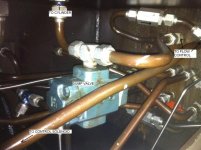
Here is a pic showing the lines between the cylinder and the bend speed flow control valve. The cylinder port this line goes to is the end with the smaller diameter shaft, which is the area that would be pressurized when bending without the double cylinder mode. The flow control is in a manifold so you cannot see the direction arrow on it, but the bypass check valve is shown with it's arrow.

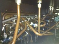
I also attached a photo showing 1/2 of the plumbing in the hydraulic cavity. It isn't pretty!

flowcontrol2.jpg plumbing.jpg
 
Hi Tubularfab,
I still think it is not hard to do as I suggested
- repipe the flow vavle
- leave the check valve where it is - no need to change
- add one DCV spring loaded in series with an additional flow control.
- this is then paralelled with the other Flow valve
- now you have two speeds available to you.
you can use an adjustable dog
or encoder value less a predetermined amount (programable)
the piping is a mess but it looks a lot easier than you may think.
I recomend you enquire with ahydraulics specialist


- then one Flow becomes the slow speed and the
 
Iant, I think your idea is good but that is not going to be cheap.
The part about enquiring a hydraulic specialist makes me laugh. A hydraulics specialist designed the mess.
Most hydraulic 'specialist' design by jingles like 'flow makes it go' and 'pressure resistance to flow' and have no idea of how hydraulics really work so they can design optimal systems.

However, Tubularfab's best option IS probably to find an integrator or hydraulic distributor that knows controls so that he can hold a single person or company responsible for the performance of the machine.
 
Your probably right Pete,
It is a shame i dont live there, it is not that hard.
But the proportunate valve would noot be any cheaper.
 

Similar Topics

Hi , Where i can find Mitsubishi PLC Card end of line & replacement model details. i am looking for Q02CPU replacement model. Please advice. thanks
Replies
2
Views
126
I have Allen Bradley plcs, I have had Circuit breakers and other automation equipment in the past. There's no solid buyers local. How much do you...
Replies
2
Views
205
can anyone has a good program to learn plc programming online. i have the basic looking into improve my skills thanks
Replies
1
Views
146
I want to monitor a couple signals in a place where there is no PLC but there is ethernet. I know I can use an AENTR or Flex I/O and a module but...
Replies
21
Views
787
I downloaded v24 for studio 5000 but can’t find where the download manager put it! Any help? I’ve done it before but can’t remember. Thanks
Replies
9
Views
395
Back
Top Bottom