Master Reset/Start from Beginning?

mj3

Member
Join Date
Jul 2021
Location
Midwest
Posts
11
I am using a Schneider Electric PLC with Zelio Soft 2 programming software. I have gotten my program completely written up, and I have checked and tested it within the Simulation mode, and I believe it does exactly what I want it to do.

However, I am wondering if there is a way to build in a "reset to beginning" or "start from beginning" function. After the program has run through its whole sequence, all physical components (cylinders, motors, etc.) are back at their starting position...which is ideal! But, I want it to start back at the beginning with no outputs energized.

The machine uses an "On/Off" switch that must be flipped to on in order to start the program, and a button has to be held down for the duration of the process. I am hoping there is a way to release the hold button, and flip the switch off, then back on, thus "restarting" the process and code.

Is this possible? I can't seem to figure out a good way to do it.
 
I think I know what you mean, for example the process has been stopped for some reason & you want it to go back to it's initial start position.
That is quite easy but depends on how you have written your program.
For example on pressing the button to run the normal program make sure all sensors & equipment are in the correct position to start with i.e. a start interlock like cylinders retracted, bed down, punch up etc.
Create a routine that if on initial start the machine is not in it's correct position so it becomes a sequence, however it will need to follow some rules for example take a pick & place machine, it's start position must be pick cylinder must be up, place cylinder must be back no part in grab.
So obviously before starting the return to home process check if any of the positions are incorrect, first operation is probably release gripper, next pick cylinder must be up before sending place cylinder back to home .
So pretty simple it is just a home routine that starts on the start cycle if not already in position.
As stated above the machine should not be able to start normal operation if out of position, it runs through the return routines in the correct order until back in home position. If your program has been written well it is possible to use the existing logic but you have two interlocks one when it starts from home position & one where it is doing the homing sequence.
You may want a separate routine for home position so for example:
a system that does the following:
1. check P&P is in home position if so is Part in place at pick station
2. Pick cylinder down
3. grab close
4. pick cyl up
5 place cyl forward
6. pick cylinder down
7. release grip
8 Pick cylinder up
9. Place cylinder retract
now a routine that returns to the home position in event of an error or stop.
1. open grip.
2. send pick cyl up
3. send place cylinder back.
it does not matter if any of the following are already in position as the logic will if you like scan each stage & if correct skip to next stage.
This is assuming that there are sensors that tell the system the positions if not then you would have to use short timers to do the operations.
 
That is kind of how I have it laid out now. The first line of logic is a set of inputs requiring the On/Off switch to be on, and the Run button to be pressed in order to satisfy Auxiliary relay "Start Process". The second line of logic is only fulfilled if both cylinders are in their "Home" position i.e. retracted, this fulfills Aux. relay "Starting Positions".

Then "Start Process" and "Start Positions" are the two series inputs that fulfill the first physical output. So I have my "home position"/starting conditions requirement built into my code already.

But I need a way to get the two cylinders back to their start position in the event of a stoppage in the procedure (i.e. if the user stops holding the Run button). I'm thinking I can achieve this by putting a "Home Reset" button that can be directly ladder-wired to the cylinder output and energize those two cylinders to return them home?

Another issue I'm running into: After the process has run its course, the cylinders have both been returned to their starting position, i.e. everything has been reset back to the starting conditions, ready to run again. But in order to get the cylinders back to their retracted starting postion, I have to energize them. Meaning that when it comes time for them to extend out again, they are still energized in the retracted position, and will not extend.

This could be worked around with some sort of reset at the end of my program that starts everything over, i.e. de-energizes all outputs and essentially "restarts" the whole program, but I can't quite figure out how to do that.
 
Also, I have been using the Coil Reset function, which seems to only allow me to run through the sequence once, as the Reset supersedes any latter Set of the coil. Is this correct, and is there a way around that?
 
What solenoids are you using are they 5 port double acting, if so the outputs only need to be energised for a short pulse, these types are like flip flops once energised the shuttle stays in that position until the other one is energised.
For example
Drive cylinder back Memory AND not Cylinder back sensor = Out cylinder
In other words it only energises when told to & de-energises when it reaches the prox/limit.
perhaps post your code in PDF format
 
N.B. I am pretty sure I am only re-stating @parky's post #2.

I think all you need is one more state, call it "All Go Home" for now,

  • to override all other states
    • i.e. conditions that trigger the "All Go Home" state are unconditional and cause the transition to "All Go Home" from any other state.
  • AND
  • to precede the "Start Positions" state
    • i.e. once entered, the process can only exit the "All Go Home" state by transitioning to the "Start Positions" state.

It sounds like [NOT "Start Process"] is at least one trigger to enter "All Go Home" state, and as noted above it is unconditional i.e. any time EITHER the On/Off switch is not on, OR the Run button is not pressed, the process transitions to the "All Go Home" state.

Everything can be coded with the canonical [Start/Stop] and [State Coil/Fault Coil] patterns (assuming ladder logic; see this link).

Start_Process All_Go_Home
--+-----]/[------------------------+------( )----
| |
+---other logic------------------+
| |
| All_Go_Home Start_Positions |
+-----] [------------]/[---------+ <== All_Go_Home seals itself in until all cylinders are in home positions

The "other logic" logic is anything that should cause a restart of the whole process, e.g. the completion of the last step, when the full process cycle has run its course, could also trigger "All Go Home".
A test of [NOT All_Go_Home] should then be ANDed with any other logic (rung) that does anything, but that should be disabled once the "All Go Home" state has been entered.

Once the process is in the "All Go Home" state, the retract output for each cylinder should be energized until that cylinder has fully retracted** and is in its home position.

All_Go_Home Cyl_1_Home** Cyl_1_Retract
-+---] [-----+--------]/[------------( )----
| |
+-( other )-+
(process)
(reasons)
( to )
(retract)
( Cyl 1 )


** the placement of that [NC Cyl_1_Home] Stop condition in that Start/Stop pattern will, I think, answer OP's other question about how to de-energize the retract output to a cylinder.

N.B. if the logic is written with a STATE integer with a value representing each state, then the overall logic is similar but the actual rungs/statements will be different, of course.

N.B. The way I suggest this means that any time the "Start Process" value is not 1 (i.e. On/Off switch not on OR Run button not pressed), then the cylinders will start moving toward home; that may or not be safe, and it may be better to simply stop all machinery movement and only activate the home Start/Stop patterns to retract the cylinders when a new, third "Home" button is held.
 
I have attached my code in PDF format the best I could. Also, I am using 4-way / 2-position solenoids. They are linked here https://www.grainger.com/product/ARO-1-4-in-24V-DC-4KB40


Yes, the problem is rungs/branches 002 and 003: there is no way to turn off [Starting Conditions] because it seals itself in unconditionally.

Update: Oh dear, there is a duplicate "destructive" write command to [Starting Conditions] in rung 022; that is considered something less than best practice, to put it politely; do not apologize, almost everyone does it - once. Yes, that rung 022 will overwrite whatever was done on rungs 002 and 003, although the state of [Starting Conditions] for rungs 004-021 will be whatever it was after rungs/branches 002+003 executed.

Easiest solution, without much thought, would be to invert the rung 022 logic, using De Morgan's Laws (NOT [a AND b] ≡ [[NOT a] OR [NOT b]]), to be the (not-)Stop logic to convert rungs/branches 002+003 into the Start/Stop pattern (and remove current rung 022 ;)).

Update II: ah, I did not read it correctly, the output on rung 022 is a Reset, so it kind of works, but note that M2 [Starting Positions] will be 1 on rungs 004-021 any time both cylinders are both in their Up/Retracted positions. Better to use the time-tested Start/Stop pattern and have all logic that affects [Start Positions] in one place, which will make debugging easier down the road. So it's not "less than good practice" per se, but an equivalent option is to remove the seal-in rung 003 and make the output of rung 002 a Set (SM2), and move rung 022 to where rung 003 is now; that is nearly functionally identical to the Start/Stop pattern.
 
Last edited:
an equivalent option is to remove the seal-in rung 003 and make the output of rung 002 a Set (SM2), and move rung 022 to where rung 003 is now; that is nearly functionally identical to the Start/Stop pattern.

I did this, as well as added a NC input in rungs 014 and 021 to act as a sort of "cutoff" for the solenoids that retract the cylinders.


After simulating, the code runs great the first time, but when it gets to the end and finally fulfills rung 003, M2 seems to be permanently reset -- i.e. I4 and I5 are still true, yet rung 004 will not close the M2 contact to proceed with the rest of the sequence.

This seems to be my main problem...no matter how I write it the program works great for the first run-thru but gets stuck and cannot continue for a second loop.
 
Wow, not a single NC - that's impressive, but I think it also complicates things unnecessarily.

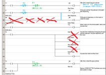
E.g. see below for an alternate approach to handle some of the logic between rungs 006-013: use negative logic (in blue) get rid of the reset - on rung seven rungs after the unconditional output - for output [Q2 Glue Down]; that also ensures the [Q2 Glue Down] will not be 1 on rungs 007-010, which does not matter in the actual case, but it could.

Update I: did the same thing with negative logic on rung 007 to remove two more offsets on rung 010.

Update II: added [NC <cylinder position>] logic (in green) to de-energize glue cylinder solenoids when cylinder reaches the corresponding stops. This resolves the problem with restarting the next cycle when the home solenoid is energized.

General comment: I don't see much wrong with the program as presented, but the general approach is ordering rungs that act in the same sequence as the process. That may be because OP is misinterpreting what a PLC does: the PLC model is that all of the rungs execute at the same time nominally; yes, I know they actually execute serially, left-to-right and top-to-bottom, and sometimes that matters, and sometimes we design the in-scan sequence so that it does matter to achieve a goal. But my point to the current OP is that each output is either 0 or one depending on certain conditions, and it is much easier to read, understand, and debug those conditions if they are co-located on one rung i.e. the one rung that ends with the output instruction that assigns the 1 or the 0 on every scan*.

* I'm not saying anything is wrong with Set/Reset instructions, just they are rarely necessary, and even when they are the better choice, then it is best to use them in pairs, and not one or the other mixed with unconditional outputs as in OP's original program.


xxx.png
 
Last edited:
...use negative logic get rid of the reset - on rung seven rungs after the unconditional output - for output [Q2 Glue Down]; that also ensures the [Q2 Glue Down] will not be 1 on rungs 007-010, which does not matter in the actual case, but it could.

View attachment 59757

So are you indicating that I should place a NC I7 input on rung 006, such that Q2 Glue Down is deactiviated when the Q2 cylinder reaches its limit switch?

That does seem to work as well, and could eliminate the reset, but I'm not sure I understand how that helps in the big picture of the issues I am encountering. Also, that may open a new can of worms and cause Q2 to be energized outside of the desired window.
 
So are you indicating that I should place a NC I7 input on rung 006, such that Q2 Glue Down is deactiviated when the Q2 cylinder reaches its limit switch?

Yes, the latest image does just that. You should do that with all of the solenoid outputs, in both directions: when the program desires the cylinder to be at one end of its travel, which desire is evaluated by and contingent on the other logic on the rung, but the cylinder is already at that end, then there is no reason to leave the solenoid activated.

That does seem to work as well, and could eliminate the reset,
not yet, but we'll get there.
that may open a new can of worms and cause Q2 to be energized outside of the desired window.


How can that happen? The logic is essentially

  • IF
    • program desires cylinder at limit X
    • AND
    • cylinder is not at limit X
  • THEN
    • activate solenoid to move cylinder toward limit X
The blue expression defines the window, so

  • IF that blue expression evaluates to false,
  • THEN by definition the process is outside that window
  • AND the solenoid cannot be energized
The red expression simply ensures the solenoid, which moves the cylinder toward limit X, is never energized if the cylinder is already at limit X.
 
Last edited:
I did this, as well as added a NC input in rungs 014 and 021 to act as a sort of "cutoff" for the solenoids that retract the cylinders.

After simulating, the code runs great the first time, but when it gets to the end and finally fulfills rung 003, M2 seems to be permanently reset -- i.e. I4 and I5 are still true, yet rung 004 will not close the M2 contact to proceed with the rest of the sequence.

This seems to be my main problem...no matter how I write it the program works great for the first run-thru but gets stuck and cannot continue for a second loop.

So what you have is a stack of timers interleaved with other conditions:

  1. [Start Conditions] triggers the bottom timer T1,
  2. and as each timer expires it triggers the next condition or timer up the stack,
  3. And when the process is done, the expiration of timer T4 AND the VC returning to home should Reset [Start Conditions] to 0,
  4. And when [Start Conditions] becomes 0, that should reset timer T1, which will eventually reset T2, then T3, etc. i.e. collapse the stack.
Step 3 is contingent on T4 still being expired, and not reset, when the VC cylinder returns to the UP home position.

And rung 019 has TT4's timing contingent on [I8 SW4(VC,D)] i.e. on VC cylinder being at its extended limit.

However, once T5 triggers [Q7 VC Up] on rung 021,

  • the VC cylinder will start retracting away from its extended limit,
  • and [I8 SW4(VC,D] will become 0,
  • and T4 will reset,
  • and rung 003 will never reset [Start Conditions] if and when the VC cylinder reaches its retracted limit,
  • for that matter, TT5 will also stop timing and/or be reset, which should put a 0 in output [Q7 VC Up], which does I don't know what to the cylinder position that may or may not have been fully retracted.
which seems to be the opposite of the problem you are actually seeing.
 

Similar Topics

Hello. I ask you to help this problem . I am currently using 02 stations located in all PACSystems RX3i . I experience this phenomenon is the 02...
Replies
1
Views
4,317
I've got a problem with an S7-416 CPU. The last time it was used, the MPI port was defined as a profibus port. Nothing wrong with that. But now, I...
Replies
18
Views
25,958
hello s7-400h and wincc are connected to each other via Ethernet. I need help on how to do time synchronization
Replies
0
Views
54
Does Rockwell still offer reset codes for old school Master Disk floppy's? In a bind and need to reset the activation disk soon and to be pointed...
Replies
9
Views
230
I have to start out by saying I am not a PLC programmer and I have basic programming skills but mainly use software as a troubleshooting tool. I...
Replies
0
Views
131
Back
Top Bottom