Mitsubishi programming help

smithers

Member
Join Date
Jan 2005
Location
England
Posts
25
Hi can you help, have a book stitching machine with collates pages in 8 stages.
I have installed a camera system that will give an input to mitsubishi FX3G plc.
Any book with a bad image needs to be rejected after book has been stitched.
The inputs to plc from the 8 camera system (1 if faulty 0 if ok) are read by plc every revoultion of drive shaft (1 pulse per cycle of machine). The status of all 8 inputs need to be remembered for each cycle so that plc knows which, if any, books need to be rejected at the reject station. I think I have worked out the code needed but it is like a million billion steps as there are 96 possible patterns for the 8 plc inputs per machine cycle, is there an easier way to do this.
Many thanks
 
Last edited:
Hi Smithers,

Are you able to post some snippets or share your code?

Why do you need to monitor all 96 patterns? Surely any "1" in your byte of data at the time of checking is automatically a fail and rejection of the book?

Is there any way to invert your bits? (as an example if there is a breakdown in communication or a fault in you camera wiring- you will end up reading zero's, which is always going to be a pass). If you are using a communication protocol, are you actively monitoring its status?


Regards
Daniel
 
Not sure exactly what you mean but at a guess you need to track the good/bad books as they travel along a conveyor of sorts so at the reject station it rejects the bad ones.
This is pretty simple done many tracking systems if my understanding is correct then you need the following ideally.
A sensor on a cog on the drive shaft of the conveyor (no need to go for an expensive encoder).
So in effect it gives so many pulses per say 10mm of travel of the conveyor.
Use a bit shift function.
So for example let's assume one camera for now.
the conveyor is say 2 mtrs long from the camera to the reject.
Every time you get a pulse from the sensor if the input from the camera is a "1" then store a "1" in the shift register bit 0, this then shifts this into the next bit Bit 1 & sets the bit 0 to 0 tready for the next pulse. lets assume it is 10mm per pulse then that means at 2mtrs 200 pulses i.e. one every 10mm
So when the bit (200) is on then reject actuates.
This is for one reject camera using 8 will depend on how they are arranged so it would be best to post a simple drawing of the layout i.e. conveyor or transport system, positions of the camera etc.
Depending on this layout it might require 8 shift registers but will not know that until the process is explained a little better, for example are these 8 camera's looking at possible 8 stages of book binding ?.

Here is an explanation:
For display purposes only showing 20 shifts

Shift register
00,01,02,03,04,05,06,07,80,09,10,11,12,13,14,15,16,17,18,19,20
bit pattern 1 = faulty 0 = ok
_0,_0,_1,_0,_0,_0,_1,_0,_0,_0,_0,_0,_0,_0,_0,_0,_0,_0,_0,_0,_1
Camera____________________________________________REJECT
So camera checks if ok or faulty when a fault is detected bit "0" of the shift register is set to 1, this moves down the shift register driven by the pulse from the proximity on the star cog, when it reaches bit 20 of the shift register the logic detects it's a 1 & rejects the book.
Simple logic but for 8 cameras there is a couple of ways to do it
Create 8 bit shift registers, one for each camera
Or 1 shift register & assuming the cameras are spread along the machine determine which bit position each camera is at & if a fault write a ! to it
For 8 shift registers then just do the above explanation 8 times but with different lengths.
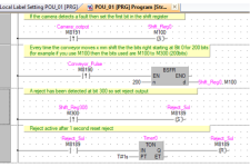
See pic of a simple 1 camera system
Note: I have used GXWorks2 & FBD language so it will depend on the programming software you have & if you intend to do it in ladder, I assume that you could also be using GXDeveloper instead of GXW2.

Reject Shift.png
 
Last edited:
Thanks for reply

Not sure exactly what you mean but at a guess you need to track the good/bad books as they travel along a conveyor of sorts so at the reject station it rejects the bad ones.
This is pretty simple done many tracking systems if my understanding is correct then you need the following ideally.
A sensor on a cog on the drive shaft of the conveyor (no need to go for an expensive encoder).
So in effect it gives so many pulses per say 10mm of travel of the conveyor.
Use a bit shift function.
So for example let's assume one camera for now.
the conveyor is say 2 mtrs long from the camera to the reject.
Every time you get a pulse from the sensor if the input from the camera is a "1" then store a "1" in the shift register bit 0, this then shifts this into the next bit Bit 1 & sets the bit 0 to 0 tready for the next pulse. lets assume it is 10mm per pulse then that means at 2mtrs 200 pulses i.e. one every 10mm
So when the bit (200) is on then reject actuates.
This is for one reject camera using 8 will depend on how they are arranged so it would be best to post a simple drawing of the layout i.e. conveyor or transport system, positions of the camera etc.
Depending on this layout it might require 8 shift registers but will not know that until the process is explained a little better, for example are these 8 camera's looking at possible 8 stages of book binding ?.

Here is an explanation:
For display purposes only showing 20 shifts

Shift register
00,01,02,03,04,05,06,07,80,09,10,11,12,13,14,15,16,17,18,19,20
bit pattern 1 = faulty 0 = ok
_0,_0,_1,_0,_0,_0,_1,_0,_0,_0,_0,_0,_0,_0,_0,_0,_0,_0,_0,_0,_1
Camera____________________________________________REJECT
So camera checks if ok or faulty when a fault is detected bit "0" of the shift register is set to 1, this moves down the shift register driven by the pulse from the proximity on the star cog, when it reaches bit 20 of the shift register the logic detects it's a 1 & rejects the book.
Simple logic but for 8 cameras there is a couple of ways to do it
Create 8 bit shift registers, one for each camera
Or 1 shift register & assuming the cameras are spread along the machine determine which bit position each camera is at & if a fault write a ! to it
For 8 shift registers then just do the above explanation 8 times but with different lengths.
See pic of a simple 1 camera system
Note: I have used GXWorks2 & FBD language so it will depend on the programming software you have & if you intend to do it in ladder, I assume that you could also be using GXDeveloper instead of GXW2.

Hi, thanks for your reply. Using GXW2 in ladder. cameras are spread along machine (one per page drop) and was going to use a shift register as that would ensure faulty images are rejected for faulty images detected on any given cycle however, as it takes between 5 and 12 cycles and cycle time is around 1 second (depending upon which camera picks up a faulty image) do I need to create a separate shift register for for every cycle of the machine.

Thanks
 
I need to check the functionallity but I don't think so
For example, if the cameras were say 10 pulses apart (effective position on conveyor)
then
Cam 1 is at bit 0
Cam 2 is at Bit 10
Cam 3 is at bit 20
Cam 4 is at bit 30
& so on
So all you need to do is for each camera set the bit associated with it's bit position.
It is just a matter of seeing how many pulses you get per x mm it's trial & error really.
If you do not want to use interrupts (not sure off hand if that model you have can use them) then the gap between the pulses from the star wheel on the conveyor need to be twice the expected scan time of the PLC so for example if the scan time of your plc when programmed is 20ms then the pulses from the conveyor must not be less than 40ms
You just set the bits corresponding to the camera position in the shift register bits
It will not matter if it is already set as if one book has 2 or more rejects from the cameras it only needs that one bit position for example fault at bit 10 & 20 at bit 10 it is already a 1 so setting it again at bit 20 is ok. it will not know if 1 or more cameras set a reject but it will know at least one did.
 
set up

Not sure exactly what you mean but at a guess you need to track the good/bad books as they travel along a conveyor of sorts so at the reject station it rejects the bad ones.
This is pretty simple done many tracking systems if my understanding is correct then you need the following ideally.
A sensor on a cog on the drive shaft of the conveyor (no need to go for an expensive encoder).
So in effect it gives so many pulses per say 10mm of travel of the conveyor.
Use a bit shift function.
So for example let's assume one camera for now.
the conveyor is say 2 mtrs long from the camera to the reject.
Every time you get a pulse from the sensor if the input from the camera is a "1" then store a "1" in the shift register bit 0, this then shifts this into the next bit Bit 1 & sets the bit 0 to 0 tready for the next pulse. lets assume it is 10mm per pulse then that means at 2mtrs 200 pulses i.e. one every 10mm
So when the bit (200) is on then reject actuates.
This is for one reject camera using 8 will depend on how they are arranged so it would be best to post a simple drawing of the layout i.e. conveyor or transport system, positions of the camera etc.
Depending on this layout it might require 8 shift registers but will not know that until the process is explained a little better, for example are these 8 camera's looking at possible 8 stages of book binding ?.

Here is an explanation:
For display purposes only showing 20 shifts

Shift register
00,01,02,03,04,05,06,07,80,09,10,11,12,13,14,15,16,17,18,19,20
bit pattern 1 = faulty 0 = ok
_0,_0,_1,_0,_0,_0,_1,_0,_0,_0,_0,_0,_0,_0,_0,_0,_0,_0,_0,_0,_1
Camera____________________________________________REJECT
So camera checks if ok or faulty when a fault is detected bit "0" of the shift register is set to 1, this moves down the shift register driven by the pulse from the proximity on the star cog, when it reaches bit 20 of the shift register the logic detects it's a 1 & rejects the book.
Simple logic but for 8 cameras there is a couple of ways to do it
Create 8 bit shift registers, one for each camera
Or 1 shift register & assuming the cameras are spread along the machine determine which bit position each camera is at & if a fault write a ! to it
For 8 shift registers then just do the above explanation 8 times but with different lengths.
See pic of a simple 1 camera system
Note: I have used GXWorks2 & FBD language so it will depend on the programming software you have & if you intend to do it in ladder, I assume that you could also be using GXDeveloper instead of GXW2.

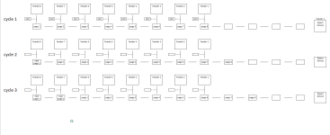
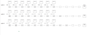
please see attached simple pic

Screenshot (29).png
 
Overkill

I think I have worked out the code needed but it is like a million billion steps as there are 96 possible patterns for the 8 plc inputs per machine cycle, is there an easier way to do this.
Many thanks

For 8 bits, with each discrete input bit having a value of 1 or 0, independent of all other input bits, there are 256 (= 28) possible patterns.

Or are we misunderstanding the process?

Can we take a step back and describe the process more fully?

For example, there is a reject station where books arrive(?) and are either rejected or not, is that correct?

Since a book can arrive at the reject station, that means the book can be somewhere other than the reject station, so it seems the books must move somehow. There are also cameras "spread along [the] machine," as well as "drops" (positions where pages are added?). How do the books move between these positions? Are they on a conveyor of some sort, as @parky suggests?

TL;DR

All computer programs are a model of something (a process or device) in the real world. A program operates on bits in memory, and those bits in memory represent the state of the process. For example, each book's reject state can be represented by a single bit, with a value of 1 if the book is to be rejected or 0 if not. Before the first page is dropped onto a book and the camera inspects that page, the value of a that book's state is 0, because there is no reason to reject it. Once an any camera detects a problem, the value of the book's bit changes to 0. Only a change from 0 to 1 is possible; subsequent camera inspections that pass cannot make a value of 1 into a 0, and subsequent camera inspections that fail would only overwrite the value of 1 with another value of 1.

An important corollary to this concept of the program as a process model is that the primary design choice is the level of fidelity of the model. The model needs to keep track of the state of each book in the system, and the cycle events of the shaft rotation, and the result of each camera inspection, but it does not need to keep track of

  • when or where pages are dropped
    • it only needs to inspect the results via the cameras, which cameras are in the model
  • operators walking around the plant
  • what the operator ate for lunch.
Alternatively, we could keep track of eight individual bits per book so we would know which of the eight drops caused a book to be rejected, however I doubt that is necessary.

Finally, PLC programming is primarily about time, and the PLC scan cycle is the clock. In this process there is another clock, which is the shaft rotation.

So the question is, how does the program deliver (examine) a bit's value of 1 or 0 for that book's reject state when that book is at the reject station? And the answer is in @parky's post: the program has a data model that uses a shift register with a single reject status bit per book. The shifting of the reject status bits' values along the register bits' positions represents the cycle that moves all books by some physical linear distance (along the conveyor?). When each shift occurs, a bit with a value of 0 is placed at the head of the shift register. It does not matter if there is actually a book at the start of the conveyor represented by the new bit. What does matter are the positions of the cameras and the reject station. "Station" comes the Latin stare, to stand, so it is a fixed position: each camera or reject position is at a fixed distance from the start of the conveyor, which start is represented by the first bit in the shift register, where new bit value of 0 written at each cycle. The distances to those stations may be measured in feet or meters, but within the program those linear units are converted to cycle counts. Each cycle represents one revolution of the drive shaft, and one pulse to the PLC input, which represents a fixed linear movement of everything on the conveyor, so converting between the linear measurements of the positions of the stations along the conveyor and the equivalent number of cycles (i.e. shift register bit positions) in the PLC program's data model should be straightforward. The point here is that the location of each camera, and of the reject station, corresponds to the position (index) of a single bit in the shift register. The input from each camera triggers

  • EITHER writing a 1 to the value of that single bit to reject the book at that position (model bit),
  • OR doing nothing (i.e. leaving the value of that bit as is, either 1 if rejected by a previous camera, or 0 if not)
The value of the bit, at the position in the shift register that corresponds to the physical location of the reject station, triggers

  • EITHER activating the reject device output if the value of that bit is 1
  • OR doing nothing if the value of that bit is 0
    • or perhaps retracting the reject device if that bit's value was 1 on the previous cycle
The assumption of the model is that, when a camera rejects a book, that book is at the camera's station, which station is represented by a single bit's position in the shift register. And the position of a bit must be distinguished from its value:

  • the value of a bit represents the reject status of a book at the that bit's corresponding position in the process
  • bit values are shifted from one position to the next on each shaft rotation, which represents books (or empty spaces) moving along the conveyor.
Another concept to understand in @parky's data model is that the program keeps track of the spaces between books, with bits that always have a value of 0. It may seem that that information is unnecessary excess fidelity of the model, but actually those space-bits are necessary to maintain the model of the positions of, and the space between, the actual books. So writing a value of 0 to the start position bit of the shift register, when there is no book at that position, places a space into the model representing one cycle's space between books on the conveyor. Since a camera will "see" nothing when a space is in front of it, the corresponding space-bit in the shift register will not change from its value of 0; also, when a space-bit value reaches the reject station's corresponding position, it's value of 0 will not trigger the reject output.
 
I see you posted a image; I assume each row represents discrete times, increasing down, in that image.

It looks like there is no space between feeder/camera stations, and one cycle (shaft rotation) moves a book completely from one feeder/camera to the next. So there will be no space between books. That's fine, @parky's model still works. The only interesting bit will be translating the physical distance, from the feeder/camera stations to the reject station, to a position in the shift register.

Note that the camera status will use a SET instruction; an output coil will not work (unless you use a Start/Stop Circuit pattern, which would work but is not as clean as the SET instruction).
 
I need to check the functionallity but I don't think so
For example, if the cameras were say 10 pulses apart (effective position on conveyor)
then
Cam 1 is at bit 0
Cam 2 is at Bit 10
Cam 3 is at bit 20
Cam 4 is at bit 30
& so on
So all you need to do is for each camera set the bit associated with it's bit position.
It is just a matter of seeing how many pulses you get per x mm it's trial & error really.
If you do not want to use interrupts (not sure off hand if that model you have can use them) then the gap between the pulses from the star wheel on the conveyor need to be twice the expected scan time of the PLC so for example if the scan time of your plc when programmed is 20ms then the pulses from the conveyor must not be less than 40ms
You just set the bits corresponding to the camera position in the shift register bits
It will not matter if it is already set as if one book has 2 or more rejects from the cameras it only needs that one bit position for example fault at bit 10 & 20 at bit 10 it is already a 1 so setting it again at bit 20 is ok. it will not know if 1 or more cameras set a reject but it will know at least one did.

Hi Parky

machine is an 8 unit page collator (1st page set drops from unit 8, 2nd page set drops onto 1st page set when it arrives at unit 7 (1 revolution of machine) 3rd page set drops onto 2nd page set that has already on previous cycle dropped onto 1st page, etc. All cameras take image at the same time within any given cycle and once machine is loaded page sets drop from all 8 units simultaneously and continuously once per cycle.

Screenshot (29).png
 
I think I know what you need to do
For example have an 8 bit word (use 16 bits as it is a 16 bit operation)
0000000000000000 Initial before start of operation
Seq. 1
0000000000010000 Feeder 5 has an error
Seq 2
0000000000000100 Feeder 3 has an error
Seq. 3
0000000000000101 Feeders 3 & 1 have an error
These correspond to bits M0 through to M15 (bits 8-15 not used)
So in effect after cycle 3
you have stations 1,3,5 in error
0000000000010101
At end of the 3rd cycle copy these to another 16 bit memory & reset all bits perhaps a move instruction.
Then as the books move out have a sensor on the reject station
When a book passes over the reject, test the bit (effective bit 0) if a 1 then reject & shift the bit patern when next book passes photocell check for 1 again & so on
Not sure about if the operation is as I think but this way you only have a simple logic but mind boggling understanding for others that do not know.
I will try to come up with some code & simulate it but it should be quite small
After all, the only code is setting the bits of an 8 bit pattern, moving that to a store, shifting the store when the books move into reject & setting reject if a bad book is in the shift register.
Hope that helps
 
For 8 bits, with each discrete input bit having a value of 1 or 0, independent of all other input bits, there are 256 (= 28) possible patterns.

Or are we misunderstanding the process?

Can we take a step back and describe the process more fully?

For example, there is a reject station where books arrive(?) and are either rejected or not, is that correct?

Since a book can arrive at the reject station, that means the book can be somewhere other than the reject station, so it seems the books must move somehow. There are also cameras "spread along [the] machine," as well as "drops" (positions where pages are added?). How do the books move between these positions? Are they on a conveyor of some sort, as @parky suggests?

TL;DR

All computer programs are a model of something (a process or device) in the real world. A program operates on bits in memory, and those bits in memory represent the state of the process. For example, each book's reject state can be represented by a single bit, with a value of 1 if the book is to be rejected or 0 if not. Before the first page is dropped onto a book and the camera inspects that page, the value of a that book's state is 0, because there is no reason to reject it. Once an any camera detects a problem, the value of the book's bit changes to 0. Only a change from 0 to 1 is possible; subsequent camera inspections that pass cannot make a value of 1 into a 0, and subsequent camera inspections that fail would only overwrite the value of 1 with another value of 1.

An important corollary to this concept of the program as a process model is that the primary design choice is the level of fidelity of the model. The model needs to keep track of the state of each book in the system, and the cycle events of the shaft rotation, and the result of each camera inspection, but it does not need to keep track of

  • when or where pages are dropped
    • it only needs to inspect the results via the cameras, which cameras are in the model
  • operators walking around the plant
  • what the operator ate for lunch.
Alternatively, we could keep track of eight individual bits per book so we would know which of the eight drops caused a book to be rejected, however I doubt that is necessary.

Finally, PLC programming is primarily about time, and the PLC scan cycle is the clock. In this process there is another clock, which is the shaft rotation.

So the question is, how does the program deliver (examine) a bit's value of 1 or 0 for that book's reject state when that book is at the reject station? And the answer is in @parky's post: the program has a data model that uses a shift register with a single reject status bit per book. The shifting of the reject status bits' values along the register bits' positions represents the cycle that moves all books by some physical linear distance (along the conveyor?). When each shift occurs, a bit with a value of 0 is placed at the head of the shift register. It does not matter if there is actually a book at the start of the conveyor represented by the new bit. What does matter are the positions of the cameras and the reject station. "Station" comes the Latin stare, to stand, so it is a fixed position: each camera or reject position is at a fixed distance from the start of the conveyor, which start is represented by the first bit in the shift register, where new bit value of 0 written at each cycle. The distances to those stations may be measured in feet or meters, but within the program those linear units are converted to cycle counts. Each cycle represents one revolution of the drive shaft, and one pulse to the PLC input, which represents a fixed linear movement of everything on the conveyor, so converting between the linear measurements of the positions of the stations along the conveyor and the equivalent number of cycles (i.e. shift register bit positions) in the PLC program's data model should be straightforward. The point here is that the location of each camera, and of the reject station, corresponds to the position (index) of a single bit in the shift register. The input from each camera triggers

  • EITHER writing a 1 to the value of that single bit to reject the book at that position (model bit),
  • OR doing nothing (i.e. leaving the value of that bit as is, either 1 if rejected by a previous camera, or 0 if not)
The value of the bit, at the position in the shift register that corresponds to the physical location of the reject station, triggers

  • EITHER activating the reject device output if the value of that bit is 1
  • OR doing nothing if the value of that bit is 0
    • or perhaps retracting the reject device if that bit's value was 1 on the previous cycle
The assumption of the model is that, when a camera rejects a book, that book is at the camera's station, which station is represented by a single bit's position in the shift register. And the position of a bit must be distinguished from its value:

  • the value of a bit represents the reject status of a book at the that bit's corresponding position in the process
  • bit values are shifted from one position to the next on each shaft rotation, which represents books (or empty spaces) moving along the conveyor.
Another concept to understand in @parky's data model is that the program keeps track of the spaces between books, with bits that always have a value of 0. It may seem that that information is unnecessary excess fidelity of the model, but actually those space-bits are necessary to maintain the model of the positions of, and the space between, the actual books. So writing a value of 0 to the start position bit of the shift register, when there is no book at that position, places a space into the model representing one cycle's space between books on the conveyor. Since a camera will "see" nothing when a space is in front of it, the corresponding space-bit in the shift register will not change from its value of 0; also, when a space-bit value reaches the reject station's corresponding position, it's value of 0 will not trigger the reject output.

Hi drbitboy
Process as follows:
the 8 units are manually kept topped up with folded page sections (a different folded page section for each unit) each have a rotating page feeder mechanism that simultaneously and continuously (once per shaft revolution) feeds a folded page set (different folded page set for each feeder) onto an inverted V conveyor which carries the folded sections left to right.
When the single shaft that rotates all 8 feeder mechanisms rotates xdegrees, all cameras take an image.
The camera control until will then switch one or more of 8 output signals to ON depending upon the result of "good" "bad" image comparisons. The state of said outputs are then reset to OFF via a one pulse per revolution shaft sensor and the system is ready for next cycle.
Not sure if allowed but video link shows how said machine operates
https://youtu.be/wvUl5O5ECgc
 
Hi drbitboy
Process as follows:
the 8 units are manually kept topped up with folded page sections (a different folded page section for each unit) each have a rotating page feeder mechanism that simultaneously and continuously (once per shaft revolution) feeds a folded page set (different folded page set for each feeder) onto an inverted V conveyor which carries the folded sections left to right.
When the single shaft that rotates all 8 feeder mechanisms rotates xdegrees, all cameras take an image.
The camera control until will then switch one or more of 8 output signals to ON depending upon the result of "good" "bad" image comparisons. The state of said outputs are then reset to OFF via a one pulse per revolution shaft sensor and the system is ready for next cycle.
Not sure if allowed but video link shows how said machine operates
https://youtu.be/fXYqTO_jSSg
 
I understand the 8 stations so it looks like 8 pages (or double pages) are placed on the V conveyor, this then moves on to some other process etc. etc.
Where does the 3 cycles come in ?.
It looks to me as if it is a continuous process i.e. a page(s) are dropped on the conveyor, the conveyor is moving in only one direction & as it passes each station it drops the next page(s). so yes it would be a continuous process according to the video but does not explain the 3 cycles.
Where will the reject station be will it be on a part of the V conveyor ?.
somewhere after the 8 stations before it goes into binding or what ever.
If so it seems pretty simple Are the cameras going to be on the stations?
I can invisage a system where you only need one shift register very little logic just a matter of getting the right number of bits of the shift register & the distances of travel sorted.
 
Last edited:
I agree with @parky, it is even simpler than we thought because the main shaft input signal is a perfect clock. The first eight bits of the register represent the positions of the eight feeder stations, there are as many bits beyond those first eight as needed to represent the position of the reject station. On every scan cycle that detects a rising edge of the main shaft input four things happen:

  • Any of the eight input values that are 1 SETs the value of its corresponding shift register bit to 1. This models cameras that found "bad" books from the cycle previous to that rising edge, and marks those books in their position in the shift register.
  • All of the cameras' inputs' values are clear to 0.
  • All bits in the register are shifted one position (let's assume a left-shift). This models the each book moving to the next position, whether that next position is a feeder station or beyond.
  • The value of the first (low?) bit, bit 0 representing the position of the first feeder station, is RESET to 0. This models a new book that has not been looked at by any cameras yet.
Finally, on every scan cycle, if the value of the bit in the register that corresponds to the position of the reject station is 1, then the reject mechanism is activated by writing a 1 to the value of the reject output, otherwise write a 0 to the value of the reject output. This models a bad book being rejected, or a good book not being rejected, at the reject station.

SET and RESET are the only instructions used to write values of 1s and 0s to any of the shift register bits; do not use coils {-( )-}.
 
If you search this forum (see "Search ▼", or "Search the forum using Google" text box, above) with the terms conveyor, bit, and shift, you should find discussions and programming examples of similar applications.
 

Similar Topics

Hi everyone, I'm new to ladder programming and I may have been too ambitious thinking I could do a full plc program by myself. My father has a...
Replies
62
Views
14,848
Hello All, Merry Christmas, Happy Holidays, and Happy New Year to all. This is my first time posting. I've been reading these forums for the...
Replies
3
Views
3,385
I have a Mitsubishi Q06UDEHCPU PLC with it being programmed in GX Developer. This is running a new Aida press in our facility. I was trying to...
Replies
3
Views
1,631
I trying to link v600 omron rfid to mitsubishi plc Qj71c24n-r4 but i not getting any response when i try to scan.i can link with omron plc with...
Replies
3
Views
2,244
I am new to Mits PLC programming so I am unsure on a few functions. I am trying a really basic sequencer, making an individual coil high for a...
Replies
15
Views
5,587
Back
Top Bottom