Mitsubishi programming help

there will be no need to reset a bits in the shift register only the first bit after the shift (I have a funny feeling even that might not be required as it should put a 0 in it). So providing the reject station is on that V conveyor the shift will be fine. As I said earlier, make the pulses say 4 or more per station & trigger the bit in the middle, not that it matters as would not need a high resolution as at the reject station you have a choice of 4 to reject i.e. on a station out of the 4 bits (detection area) it happens to be bit 2 then when that gets shifted to the reject perhaps allowing for delay or actuation time any of the 4 bits on that station could be used to initiate the reject (window).
done this so many times one had a shift register of 2000 registers with a simple barcode, on a conveyor ring, there were 17 divert stations when the read barcode matched a station it diverted it onto another conveyor, if no barcode matched it returned round the loop & merged with the oncomming feed.
 
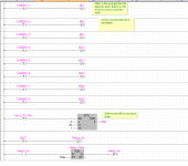
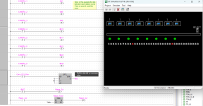
Here is a very quick one I did, I used FBD because all the code fits on screen easy rather than ladder note I have included a quick mashup of an HMI screen I used to simulate it i.e. buttons to initiate the cameras, note the bit pattern below the camera stations just to show how as the conveyor traverses the bits move so for example on station 1 if a camera gives a 1 then that is stored in bit 1 (not bit 0 as this should be 0 so the shift puts 0 into bit one after it is shifted) of the shift register, here I have only 38 or so shifts but it will deend how many pulses you get per say 100 mm of conveyor, if you like the camera 1 or 0 tracks the book as it moves along the camera, when a book gets to the reject station if the bit at the reject station (might be say 4 bits wide) but just use which of the 4 bits trigger the reject so it catches the book.

Binder code.png Binder.png
 
Thanks Parky

I understand the 8 stations so it looks like 8 pages (or double pages) are placed on the V conveyor, this then moves on to some other process etc. etc.
Where does the 3 cycles come in ?.
It looks to me as if it is a continuous process i.e. a page(s) are dropped on the conveyor, the conveyor is moving in only one direction & as it passes each station it drops the next page(s). so yes it would be a continuous process according to the video but does not explain the 3 cycles.
Where will the reject station be will it be on a part of the V conveyor ?.
somewhere after the 8 stations before it goes into binding or what ever.
If so it seems pretty simple Are the cameras going to be on the stations?
I can invisage a system where you only need one shift register very little logic just a matter of getting the right number of bits of the shift register & the distances of travel sorted.

The reject device is at the end of the V conveyor and I have already installed a sensor at that point. Yes, there is a camera on each station and believe your solution will work however, although I have Programmed dozens and dozens of mitsubishi PLC's I am self taught and have never had the need to use shift registers and I am unsure as to how to write the code as I am only familiar with ladder logic.
Any help with code will be appreciated.
 
... I am self taught and have never had the need to use shift registers and I am unsure as to how to write the code as I am only familiar with ladder logic.
Any help with code will be appreciated.


0) Bit shifts may be a black box to you now, but once you understand what they do, you will probably be able to implement the necessary code; it is not very complex in the end, but it requires understanding a few aspects of PLCs. Some of the rest of this may already be in your toolbox.

1) PLC programming is primarily about time, and the scan cycle is the clock. It is far more useful to ask yourself when something is happening than what is happening. To understand I suggest watching this video series. https://www.youtube.com/watch?v=T3tnXu-Eywc&list=PLB1ACAF773A15BFB1

2) PLC programs implement nothing more than a model of a real-world process using bits. Understanding how bits model (represent) that process is crucial to PLC programming, because the only thing you can do in a PLC program is change bits and move bits' values around; see (1) above.

2.1) Do you understand

2.1.1) what a discrete bit (input, or output, or memory) is by itself, and what its possible values are?

2.1.2) what a bit is in an aggregate entity like an integer, and what its possible values are, and those values represent in the aggregate?

2.1.3) what a bit is in an array of integers or bits of a bit-shift array, and what those bits' values model (represent) in the real-world process, and what those bits' location' model?

2.1.4) what does shifting the bit values in an array of integers or bits of a bit-shift array model in the actual process?

3) Do you have the Mitsubishi programming manual?

3.1) If yes, do you understand how the bit-shift instructions work, and how they move bits' values around, and how that models your process?

3.1) If you do not understand how the Mitsubishi bit-shift instructions work, try a better manual from another brand e.g. here. https://literature.rockwellautomati...re/documents/rm/1756-rm003_-en-p.pdf#page=505

3.1.1) I have found that the various brands of PLCs' implementations of the various sets of instructions are more or less the same. Some IDEs and ladder syntax rules are better, some are worse, but all are doing more or less the same thing.

4) Note that a bit shift instruction shifts bits only on the rising edge of its input rung.

5) Does Mitsubishi have a PLC emulator where you can play with the bit-shift instruction to understand its behavior?s

5.1) If not, try another brand e.g. RSLogix Micro Starter Lite and RSEmulate 500 are freebies that that you can experiment to understand bit shifting, then you should be able to transfer that knowledge back to Mitsubishi-land.

5.1.1) Note that, despite 3.1.1 above, instructions may not operate identically across brands, so after you understand what a bit shift instruction does from another brand, go back to the Mistubishi manual and with that new knowledge re-read the description of the Mistubishi bit shift instruction, to see if (i) you can now understand the Mitsubishi description, and (ii) if there are any differences in how the Mitsubishi bit shift instruction works.

6) Search this forum for keywords bit shift, conveyor, and reject station, to find threads about processes similar to yours.

6.1) Read carefully any posts by @parky.

6.2) Look at the various programs posted and ask any questions you have about them here.
 
Hello again

I understand the 8 stations so it looks like 8 pages (or double pages) are placed on the V conveyor, this then moves on to some other process etc. etc.
Where does the 3 cycles come in ?.
It looks to me as if it is a continuous process i.e. a page(s) are dropped on the conveyor, the conveyor is moving in only one direction & as it passes each station it drops the next page(s). so yes it would be a continuous process according to the video but does not explain the 3 cycles.
Where will the reject station be will it be on a part of the V conveyor ?.
somewhere after the 8 stations before it goes into binding or what ever.
If so it seems pretty simple Are the cameras going to be on the stations?
I can invisage a system where you only need one shift register very little logic just a matter of getting the right number of bits of the shift register & the distances of travel sorted.
Hi Parky, Thanks.

Reject station is at end of V conveyor and there is a camera on each of the 8 units and I have installed a sensor just before reject station.
Your solution is good my problem is that, although I have have programmed many Mitsubishi plc's I am completely self taught and have never had the need to use bit shift registers and only use ladder logic so I am unsure about the code.
I would be extremely thankful if you could give me an example of code required using ladder logic.

Many thanks
 
I can certainly do that, just need a little time.
Things you need to think about.
There are two ways of generating the conveyor pulses, a star wheel with proximity, this gives you a pretty accurate pulse per say mm of conveyor movement, however, you could just use either one of of the built in clock pulses for example the 0.1 second clock & use that, however, this may not be as accurate it will depend on the number of pulses generated & the conveyor speed would have to be constant not ideal.
You will need to work out the number of pulses generated when the conveyor gets from station 1 to the reject, an example is let's say the distance from station 1 to the reject is 2 metres & the pulse equals 10mm then the bit shift register would be 200 pulses or 200 segments of the shift register .
Readers & Reject
-----| 1 |----------|----2----|--------//-----------| Reject |
Bit 0 to 200 of shift register
-----0000000000000000000000000000000000000000000000 Shift register
The bits shown as "1" are where the camera would trigger or the reject
-----00010000000000000010000000000000000000000010000000
so in this example we have some (maybe only one bit in the shift register not used i.e. bit 0 to bit 2, this is because when the bits are shifted you need to have a 0 so if cam 1 put a 1 in 3 the shift causes the unused bits that are 0 to move if you used bit 0 as the cam 1 then it would stay at 1 & you would have to reset it after the shift.
so bit 3 is the bit you set for cam 1 bit 16 for cam 2 & so on.It's just a matter of determining the bits you need to set or use, in the example above it is assumed it will be the bit that corresponds to the middle of the station, this is also the same at the reject station, however, you can use any of the bits in the "Window" of the stations, this is helpful on the reject station due to reaction time of the reject, you have a sensor on this so not so important, but I do suggest that you look at say at least 3 bits in this area as the trigger.
Remember, if you want to use a standard input & not use interrupts then the pulses must be at least 2 times the scan rate of the plc so if your plc scan time is 20ms then the pulses cannot be faster than 40ms this is to ensure every pulse is captured, or use interrupt input if you need faster pulses.
EDIT: this is difficult to show alignment on here as the font causes lines to shift so the shift regiser & cam triggers are out of line once posted, but look correct in the editor
 
Last edited:
Here you go:
Note to keep it easy for me to junk this code quickly, I have just put in that the pulses are about 10 per station to station, however, you will need to work out what they will be based on the number of pulse it takes between stations etc.
I have used all internal bits for the real Input/outputs you will use so I could easily simulate it.
Basis of operation, imagine the conveyor is split into segments i.e. one pulse = xmm of conveyor movement, so assume the bit shift register bit 0 is the start of the first camera station, then bit 3 is where the camerav is, then if there is an error this is set to one, as the conveyor runs this bit is shifted along the shift register, the same goes for all the other stations, if it happens that a second station camera generates an error it then sets the bit at that station, it is possible that the bit at that station is already a "1" because the previous station detected an error when the book was on it's station so it still is a 1.
There is a slight catch however, if for some reason the stations were slightly difference in their spacing then at some stations it may set a bit either side,
Example:
00000000000001100000000000
Assume station 1 set a bit as an error then station 2 it may not be quite in alignment perhaps due to conveyor slip or slap due to worn parts so in effect station 2 instead of setting the same bit it set a bit either side of the expected bit so you end up with two, it may be prudent to have a window of bits on the reject station i.e. OR say 3 bits rather than 1 so when the PE senses the book is on the reject it does not miss a reject where for some reason it is either side of the one it should have been in an ideal world, I had this on a very long system where a bar code was read & put into a word shift register 2000 words long, on one divert station on the odd occasion the shift position at the divert station did not match it was out by one shift on occasions, so I just checked for 3 of them.
 
Hi smithers,
Just some ideas to think about. Does your stitcher detect if a pocket misfeeds (the sig falls on the floor instead of going on the chain)? Many stitchers will stop the following pockets from feeding if the preceding pockets have missed. If that is the case with your stitcher than you could possibly send a "Misfeed" signal for the pocket with the bad camera image. That way if the first pocket misfed the following 7 pockets would not feed their product onto the chain. The shift register would already be programmed into the stitchers main controller and you could just hijack the "misfeed signal" with your camera signal. This works well on Heidelberg Stitchmasters.
 

Similar Topics

Hi everyone, I'm new to ladder programming and I may have been too ambitious thinking I could do a full plc program by myself. My father has a...
Replies
62
Views
14,848
Hello All, Merry Christmas, Happy Holidays, and Happy New Year to all. This is my first time posting. I've been reading these forums for the...
Replies
3
Views
3,385
I have a Mitsubishi Q06UDEHCPU PLC with it being programmed in GX Developer. This is running a new Aida press in our facility. I was trying to...
Replies
3
Views
1,631
I trying to link v600 omron rfid to mitsubishi plc Qj71c24n-r4 but i not getting any response when i try to scan.i can link with omron plc with...
Replies
3
Views
2,244
I am new to Mits PLC programming so I am unsure on a few functions. I am trying a really basic sequencer, making an individual coil high for a...
Replies
15
Views
5,587
Back
Top Bottom