Mitsubishi Q Series: PLC over-reading K-type thermocouples. Why?

A type K thermocouple is not suitable to measure those low temperatures, you should use a PT100 RTD probe that is much more accurate for that temperature range and of course change the Mitsubishi module for another for RTD probes


Type K thermocouple is suitable for temperatures above 500-600ºC up to 1100-1200ºC
 
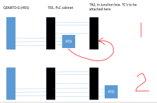
The RTD in the diagram in post #10 should be reading the actual screw terminal temperature (not the air temperature). The RTD is providing the cold junction reference temperature.


The PLC's reported temperature is the sum of the cold junction reference temperature and the 'hot junction' temperature, the mV generated by the T/C, or the calibrator, measured at the terminal block connection.


The typical symptom of the absence of any reference temperature in thermocouple thermometry is usually a reported temperature that is too low; low by whatever the temperature of the terminal blocks is, generally 25-30 Deg C.


Some devices will default to a fixed reference temperature if the CJ/reference temperature fails or is not available.


Does the 2nd terminal block even have an RTD to measure the reference temperature? If it's missing, then does the PLC default to a fixed reference temperature?
 
Does the 2nd terminal block even have an RTD to measure the reference temperature? If it's missing, then does the PLC default to a fixed reference temperature?
No, the second terminal block does not have an RTD (pic 1). I've now moved the RTD from TB1 to TB2 on some spare wires (pic 2) and the temperature reading at the PLC are now accurate. Hope this picture helps.

Capture.PNG
 
I suspect then that the cables from TB1 to 2 then are not the correct cables (possibly multicore) or the addition of extra terminals are creating a second cold junction as I explained before. So moving the RTD has now compensated for the extra TB.
It would be normal practice to ensure the TC cables go directly from the TC to the card to eliminate reflective cold junction problems down the line.
You would probably find that connecting the TC directly to the card without the RTD compensation would give a reading not far from the true.
When I have used TC's I always wire them directly to the card or at least use correct TC connectors rather than normal terminals.

Correct, the cable between TB1 and TB2 is multicore.
Not sure why it was done this way. I would've preferred to wire the TC directly to the PLC.
 
You need to make sure that correct thermocouple extension wire is used from probe all the way back to input card. If you have terminal blocks, you must use specific thermocouple terminal blocks. The CJC reference needs to stay at the input module and it should be the only place where K wire connects to copper (of the input module itself).
 
You need to make sure that correct thermocouple extension wire is used from probe all the way back to input card. If you have terminal blocks, you must use specific thermocouple terminal blocks. The CJC reference needs to stay at the input module and it should be the only place where K wire connects to copper (of the input module itself).

Thanks for this. The terminal block was installed a few years back. It's a double deck WEIDMULLER 1021500000, so not TC-specific.
 
Good drawing.

The terminal blocks are remote terminal blocks so the CJ reference temperature has to be

- monitored on the remote terminal block
- used by the PLC to calculate the reported temperature for thermocouples connected to that remote terminal block.

The wiring between the remote terminal blocks is copper wire, which is fine, because the CJ reference temperature is measured at the terminal block and RTD's do not need alloy extension wire like thermocouple do, RTD's use copper wire.

There might be some company that sells alloyed thermocouple extension wire for remote terminal blocks, but I don't know who that is; the ones I've run into do the CJ reference measurement with an RTD or thermistor so copper wire can be used for cabling from the remote terminal block to the PLC.

Cheers for this, danw. Appreciate your input..
 

Similar Topics

Hi One of the PLC's that I maintain/update is a Mitsubishi Q-Series, probably installed about 10 years ago. At the moment, ALL the wires from...
Replies
13
Views
1,173
Hello everybody! I found option for creating communication with Q series via python. But can't find any tips for connecting with PLC FX series...
Replies
3
Views
5,421
using Q03UDV plc &QY42P for outputs.....working ok i want to use new output ..download the programm but output does not show 24 v in...
Replies
16
Views
3,249
Hi, I need to send a digital output to turn a water pump Inverter driver ON/OFF. To this end, I'm planning to use a Digital Output Module, i.e. it...
Replies
16
Views
3,539
Back
Top Bottom