Normally open, Normally closed, ladder logic

dome1987

Member
Join Date
May 2014
Location
Finland
Posts
12
Hi,
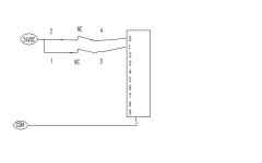
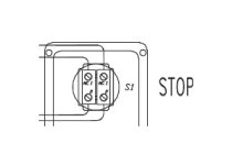
Im wondering how i have to make the circut for a emergency stop that have to normally closed relays and a push button. When i push the button i want both of the relays to be true and a lamp that show me that the emergancy stop is working. How will i write this in ladder logic and what are the inputs, how will i wire it in the real world.

Hope any one can answer and thank you
Screenshot.jpg
 
You don't use a PLC for Emergency Stop Functions.

1 - Unless the PLC is designed to for safety circuits.
2 - Or if the machine has very low danger levels and you design in diversity to the Emergency Stop system.
 
Its just for testing if the emergency button works, like a teststation. Im wondering how to write this in ladder logic... Is one nc one input and the other one an other input? Is the wire just connected with 24 VDC to neutral?
 
The relay should be false/Off when the emergency stop is pushed in not ON. Power removed ( fail safe, this way if there is a open circuit the system would be OFF, instead if wired as you suggest and there was an open circuit in the stop circuit it would stay going). So any lamp that you want to come ON will need to be thru a AUX N/C contact on the relay.
RE-PLC ladder code, if it is an "emergency stop" the requirements are that they have to be hard wired (i.e like relays) and not controlled thru a PLC (unless it is a safety PLC), or is this for indication ONLY and not the process emergency stop control circuit?
 
This is just an indication, its just for testing no real emergency stop circut! Its going to be a lcd with led buttons that show if you push the emergency button the led should light up so i now that the circut is right wired.

Iam not sure how to wire the inputs to the plc, like is one input one nc or? Like how many inputs is on the picture? And how to write it in ladder logic?

Thank you
 
I think the OP is not talking about machine safety guys

With safety devices there are a lot of regulations. This is why you are getting these answers

For TESTING ONLY

The stop button when pressed needs to open the control circuit in
Either PLC or Relay logic

Should a wire break then ideally you need the device to still stop

For this reason the 'safety' a stop button uses normally closed contacts.

(In safety applications these are twin contacts and specially monitored)

As far as indicating the buttons is pressed either
1. Use an additional Nornally Open contact to turn on a light (if 3 contacts avail)
2. Wire e.stop to relay use additional contact from relay
3. Many additional options if through a PLC
 
Ladder logic

Thank you everyone for answering.
I was more interesting how to write the program in ladder logic, so that i press the button down a led light lights upp showing that the NC NC circut works?


Thank you
 
What PLC are you using?, l know you want some code, but why do you need any PLC code when it is on a test bench, testing a stop button. Do you have a PLC just to test a N/C contact?, you can do this with a meter.
You could do this via hard wiring as well, what is the gain in the extra effort in running some wires to a PLC, unless you just want to do it as a learning project?
-||-----------------------------------( )
stop Relay input to PLC PLC output/LED light

yes i now but its much more than stop buttons and many many controllers so it would be easier with a plc so i can test all the controllers. But thank you everyone for replying
 
Welcome to the forum.

A as first step I suggest you stop thinking about the plc instruction --]\[-- as a normally closed contact and the --] [-- instruction as a normally open contact. They are not contacts, they are computer instructions that tell the cpu to check a specific bit address in memory and see what is there.

--]\[-- looks to see if a 0 is in memory.

--] [-- looks to see if a 1 is in memory.

So if you wire a normally closed contact to a PLC input, and the contact is closed, then you have electrical power at the input and thus you have a 1 in memory. Hence you must use the --] [-- instruction to see if the memory address has a 1.

Break the normally open/normally closed habit now or you will have lots of trouble down the road.

Edit to add:
It this were a real safety circuit I would wire the normally closed contacts of the E-stop buttons in series to a safety monitoring relay. I would also install a second non-safety normally open contact block on the button and wire it to the PLC input. This second contact is for identifying the button that was pressed and monitoring, but it does not do any critical safety control.
 
Last edited:
Talk about the cat amongst the pigeons.
There are many ways to learn PLC'S.
Remember that the AB range use their language XIO XIC
These were not Originaly done this way.
Remember the LD, LDI etc. instructions in mnemonic format.
The terms 'normaly' closed or open was used in relay logic to describe the state of a device when it was powered down. Well before PLC'S existed and would translate directly into Boolean logic. (A) and (not A) That is where the 0 / 1' where introduced.
The early PLC designers introduced Relay ladder logic graphical programming because that was the industry standard at the time.
There were many attempts at different formats after that.
Some fell over very quickly, because we needed field people to be able to understand and fault trace quickly.
Remember laptops/notebooks did not exist in the beginning

Sorry but I say
Learn ladder logic, understand the principle of N/O and N/C
Then understand when N/O device has logic 1 applied it allows power to pass through

We explained the Safety issue earlier. Not a concern to the OP
 
How to put togheter?

Thank you everyone for your help.

Can i wire the inputs like the picture or is there any other(better) way of doing this. Have to remember that it is more contacts and more different models.

Assembly.jpg Screenshot.jpg
 
I think people are confused because you're using dual N/C contacts for your monitoring inputs and using two relays when these are usually reserved for the actual hard-wired safety circuit. If it's just for indication, you don't need to use two contacts for your E-Stop. You certainly can if you want to, but it's a waste of inputs. Use the two N/C contacts for the actual safety circuit and install a third N/O contact on the button if you can. Wire that N/O contact into the PLC and then it's as simple as:


E-Stop N/O Input Indicating Lamp
-------------] [------------------------------( )


Similar Topics

Maybe I'm getting confused because of all the topics on XIO/XIC or NO/NC instructions but I'm just looking at my PLC relay outputs on my...
Replies
10
Views
4,302
Hello, my name is Steve and im completely new to programming and using plc's Ive had LogixPro sim for 4 days now and sucessfully managed to...
Replies
13
Views
17,262
hii,i am new to plcs and need to know about NC and NO. when power is supplied through both NO contact,it closes and powre flows through the rest...
Replies
31
Views
56,190
Hi folks, As discussed a while ago, the normally open/closed feedback newsletter issue has been distributed. (should arrive in the coming hours)...
Replies
15
Views
72,088
Andrew Groff
A
Safety for a motion system that is like 30ft+ in the air and not normally accessible? We are looking at designing a sprayer that moves back and...
Replies
7
Views
2,071
Back
Top Bottom