You are using an out of date browser. It may not display this or other websites correctly.
You should upgrade or use an alternative browser.
You should upgrade or use an alternative browser.
Normally open, Normally closed, ladder logic
- Thread starter dome1987
- Start date
Dome, as l previously asked, what type of PLC you are using as someone will have the Software and can write the basic code for you to follow. As you can see by the posts, people are willing to help but are very wary of giving code once you say "emergency stop" due to it possible being put into a process, without all the process controls taken into account. I imagine you thought the answer would be less drawn out, but more info at the start saves a lot of questions later on.
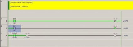
For TESTING ONLY, you want to check that BOTH contacts are CLOSED when the e-stop button is OUT (not operated), and that BOTH contacts are OPEN when the e-stop button is pressed IN (operated).
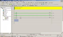
So the logic might look something like PIC#1.
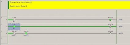
However, depending on the speed of your PLC and its I/O, it is possible that the contact blocks could change state with a finite time delay between them, and your inputs could be "acquired" during that delay. To overcome this, I would use a timer to "mask" this effect, as in PIC#2.
You will need something to unlatch the "Failed" Indicator.


@duckman, mate, the OP wants to try his knowledge.
If you do all the programming for people they then need to spend the time understanding you method.
it is better to take a less active approach and guide people rather than do the work for them.
You know apprentices need training not feeding
If you do all the programming for people they then need to spend the time understanding you method.
it is better to take a less active approach and guide people rather than do the work for them.
You know apprentices need training not feeding
I agree totally Ian, but he seems to be struggling with a N/C or N/O input and wanted code from the first post, without saying what PLC he has. I was going to leave it to you to write the code anyway,ha ha.
I must admit you gurus on this site bend over backwards to help people, when if this was happening on site, I'm sure you would wonder why some people are allowed to walk around with a screw driver in there pocket, let alone are allowed to use it.
I must admit you gurus on this site bend over backwards to help people, when if this was happening on site, I'm sure you would wonder why some people are allowed to walk around with a screw driver in there pocket, let alone are allowed to use it.
an emergency stop is normally having two NC contacts, one is going direct to the safety related items like big contactors etc.
The contact is used from the 24 V line direct to the common of the outputs, thus when pressed disabling these outputs direct without any electronic in between.
the other contact can be used to see if button is pressed.
yes lket it go to input1 for example
in the ladder put a contact and find the slash, this makes a NO to a NC
this way when there is 24 volts on input the output will be off
I agree totally Ian, but he seems to be struggling with a N/C or N/O input and wanted code from the first post, without saying what PLC he has. I was going to leave it to you to write the code anyway,ha ha.
I must admit you gurus on this site bend over backwards to help people, when if this was happening on site, I'm sure you would wonder why some people are allowed to walk around with a screw driver in there pocket, let alone are allowed to use it.
I can tell you we do get very tired of the same questions.
usually we know when the 'Final Project' or exams are due.
and these guys then walk into the jobs and have the nerve to ask us how do do their work.
Contacts
Thank you but i need both NC NC to show so i now that both of them working properly before shipping the product away!
I0.0 I0.1
-------||----||-------( )
And when i press the button on top its gonna go low and the light is illuminated showing that the circut is properly wired? As i said its just one connection of 100 different with relays and leds etc.
Ian thats why you guys are on the big bucks, $00.00hr giving $300hr training.
My best wishes to all the people who offer there hard earned knowledge away for free and as l have seen before and posted to Lance, a lot of the time you don't even get a thank you or even a final post from the poster re the help you have given.
My best wishes to all the people who offer there hard earned knowledge away for free and as l have seen before and posted to Lance, a lot of the time you don't even get a thank you or even a final post from the poster re the help you have given.
Thank you but i need both NC NC to show so i now that both of them working properly before shipping the product away!
I0.0 I0.1
-------||----||-------( )
And when i press the button on top its gonna go low and the light is illuminated showing that the circut is properly wired? As i said its just one connection of 100 different with relays and leds etc.
I0.0 I0.1
-------||----||-------( )
And when i press the button on top its gonna go low and the light is illuminated showing that the circut is properly wired? As i said its just one connection of 100 different with relays and leds etc.
Thank you but i need both NC NC to show so i now that both of them working properly before shipping the product away!
SHIPPING
Are you now talking about an actual safety application
IF SO THAN FORGET ALL WE HAVE SHOWN YOU _
THIS IS NOT A SAFETY FUNCTION IN ANY WAY
Similar Topics
Maybe I'm getting confused because of all the topics on XIO/XIC or NO/NC instructions but I'm just looking at my PLC relay outputs on my...
- Replies
- 10
- Views
- 4,304
Hello, my name is Steve and im completely new to programming and using plc's
Ive had LogixPro sim for 4 days now and sucessfully managed to...
- Replies
- 13
- Views
- 17,264
hii,i am new to plcs and need to know about NC and NO.
when power is supplied through both NO contact,it closes and powre flows through the rest...
- Replies
- 31
- Views
- 56,191
Hi folks,
As discussed a while ago, the normally open/closed feedback newsletter issue has been distributed. (should arrive in the coming hours)...
- Replies
- 15
- Views
- 72,091
A
Safety for a motion system that is like 30ft+ in the air and not normally accessible?
We are looking at designing a sprayer that moves back and...
- Replies
- 7
- Views
- 2,071


