Omron Input Pulse to SET instruction

valerianlin

Member
Join Date
Feb 2017
Location
ontario
Posts
18
Hi all,

I am fairly new to PLC programming, and just have a simple program regarding an unlatching input. In the picture below, I have STARTCOIL going to the set instruction for a single acting cylinder, LOCATOR_F. My problem is that once the STARTCOIL is actuated, it stays on, and I cannnot use the RSET instruction on LOCATOR_F.

How would I modify the program to make the STARTCOIL pulse once to set the SET bit, but after that, there is no powerflow through STARTCOIL. In short, I'd like to stimulate a non-latching push button, pushed once then released.

I would appreciate any help.

Thank You

Capture.JPG
 
It looks like you are programming in CX-Programmer. Depending on the model of PLC there is several ways to accomplish this.
I would use the differentiation on the contact. In CX-Programmer double click on the STARTCOIL contact, then hit Detail>>. At the bottom left of the window you will see the options available.
Differentiation Up means it will only be on for one scan when the input transitions from off to on.

Hope this helps you out.
Regards,

Diff Contact.PNG
 
Hi glshort, thanks for your reply. This is what I was looking for. However is there a way to make the differential up execute more than one scan cycle? Is there an instruction to reset the scan cycle/differntial up contact without going offline?
Thanks
 
The differential up will turn on for one scan from a transition from off to on. This will do this every time the input transitions from off to on.
You cannot reset the differential up instruction. It is only on for the single scan during the transition. This will be enough to set your output.

You can write additional code to make a bit turn on for as many cycle counts as you like before turning off.

There are some good examples complete with timing charts in the programming manual of the differential instructions.
What Omron model number are you programming?

Regards,
 
I am using the cs1g cpu43, which does support up and down differential. The reason i want the startcoil to act as a push button when it is energized is because there is a need to actuate that solenoid multiple times in the code, forward and reverse.
 
The Set / Reset instructions only need the one scan to turn on/off the bit. Remember that the PLC scans left to right, top to bottom. The output on one rung of logic is available for the next rung to use.
http://accautomation.ca/understanding-the-plc-program-scan/

Since you want to activate the solenoid multiple times in the code, be aware that the last time you turn it on or off will overwrite the previous operations.
You are correct in using the Diff Up to Set / Reset the solenoid.

Regards,

Thanks ! That helped solved one problem I had. Now what if I wanted to add a a reset button? How would I go about resetting the differentiating up bits if they are only on for one scan cycle without going offline?
Thank You
 
You do not have to reset the differentiating up bits.
Example: If you have a proximity sensor wired into the input of the PLC. Using a differentiation up on the input the input will be on for one scan during the transition from off to on. When the sensor turns off and then turns on again, the input would then turn on for another scan.

https://www.scantime.co.uk/_docs/Om/CS1_CJ1%20PROG%20MANUAL.pdf

"A differentiated instruction has an internal flag that tells whether the previous value is ON or OFF. At the start of operation, the previous value flags for upwardly differentiated instruction (DIFU and @ instructions) are set to ON and the previous value flags for downwardly differentiated instructions (DIFD and % instructions) are set to OFF. This prevents differentiation outputs from being output unexpectedly at the start of operation."

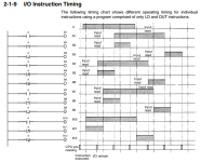
Attached is the timing chart from the manual.

Regards,

Omron Difu Instruction Timing Chart.png
 

Similar Topics

Omron AD081-V1 Analog Input Card Offset & Gain Adjustment Entering Adjustment Mode 1. Set the input card in adjustment mode (Turn ON Dip SW No-1)...
Replies
0
Views
88
Hi everyone! I have an issue with some Omron CP1L-E PLC's. They're connected to get the info from production machines, but I've noticed that...
Replies
2
Views
1,153
Hey all. Have a Omron NB5Q HMI, looking to integrate a handheld RS232 barcode scanner to input codes. All well and good for the numeric input...
Replies
1
Views
2,284
Hi I am setting a system up as per the attached picture, 5 inputs that are always present. These are sensors I have in an injection mould, if...
Replies
5
Views
1,863
Dear all, I altered a program with a new Analogue input card. So far so good everything is working fine only that an input that used to work...
Replies
1
Views
1,167
Back
Top Bottom