On Delay and Off Delay timers help

sanzen

Member
Join Date
Mar 2015
Location
America
Posts
3
I am an aspiring control systems engineer. I have a lab right now that we use plcs and programs to control what motors do. I am racking my brain trying to figure out how to do this project that I have due.
Code:
  [B]PLC Timer Project 6A (on delay) and 6B (off delay)[/B]
  
  [B]6A Project[/B]
  
  Whichever motor is selected by the switch will start first.
   
  The other motor will start after 10 seconds
   
  If either overload is tripped both motors will stop immediately and neither can be restarted until the overload is reset.
   
  Changing the selector switch position while running will cause both motors to stop.
   
  [B]6B Project[/B]
  
  Both motors start when a Start button is pressed.
   
  When stop is pressed the motor selected by the switch will stop immediately. 
   
  The other motor will stop after a 10 second delay.
   
  Changing the selector switch position while running will cause both motors to stop.
   
  If either overload is tripped both motors will stop immediately and neither can be restarted until the overload is reset.
   
  [B]PLC Inputs[/B]
  
  Stop
  Stop
  Start
  Start
  SS 1 Position 1 (Motor 1)
  SS 1 Position 2 (Motor 2)
  SS 2 Position 1 (Program 1)
  SS 2 Position 2 (Program 2)
  NO Overload Contact M1
  NO Overload Contact M2
   
  [B]PLC Outputs[/B]
  
  Motor 1
  Motor 2
I have everything to work save for having the selector switches killing the motors when either of the selector switches are flipped. The selector switches are dual position and they can only have a normally open contact block on the back of them. I can't add a normally closed contact block and then just add another input into the program.

My professor gave me a few hints but a couple of us tried to do what he suggested and failed miserably.
Code:
[LIST]
[*]Have ONE rung control ONE motor.  Having several rungs try to write to one output is a recipe for disaster.
[*]Use BINARIES.  Five of them will help you immensely
[*]Remember that you can use the DN bits of timers in more than one place
[*]The entire project can be completed with one on-delay timer and one off-delay timer
[/LIST]
We are using rslogix 500.
Does anyone have any suggestions?
http://imgur.com/52IMVeR,4DzckLj
I can post the .rss file if it is needed.
I am not trying to cheat on this or anything but 2 out of the 20 people in my class figured this out and they aren't willing to help out.
Any help would be appreciated.

file: https://livedelhi-my.sharepoint.com...TB5E=&docid=0dbc5dc3f66964b4299d287201a8a63c8
 
Last edited:
Hello and Welcome to the Forum.

Yes please go ahead and post what you have done so far.

That way forum members can look at your thought process and point you in the right direction.

Zip your .RSS file first. (Forum Rule)

BCS
 
What you need is to be able to detect "the switch was just flipped". You don't care whether it was switched from on to off, or off to on - only that it was switched.

Have a look at the ONS instruction. I would suggest that you will need two of them. Try to create a "switch turned on" pulse and a "switch turned off" pulse, that comes on for once scan when you turn the switch on or off respectively. Then I'm sure you can figure out what to do with those bits :)

Good luck!
I am running the lite version of the program on my laptop as the lab is closed right now and I can not use the ONS function but I can use the OSR command.
We haven't learned how to use that yet but from watching a few videos and reading about it, I think I understand what it will allow me to do.

If I put a OSR command in, it will energize long enough to run the timers but will die after the timer energizes but power will still but running to the timer instruction and everything will work until I flip one of the selector switches and then the motors will die.
 
The OSR works slightly differently to the ONS, but you can use this one just as easily. From the help file:

"When the rung conditions preceding the OSR instruction go from false-to-true, the OSR instruction is true for one scan. After one scan is complete, the OSR instruction becomes false, even if the rung conditions preceding it remain true."

So if you do this:

Code:
     Switch                 B3:0/0
|------||--------------------[OSR]

Then B3:0/0 will be true for ONE SCAN ONLY when your switch turns on. It will then remain false until you turn your switch off and back on again.

From there you should be able to work out how to make another bit become true for one scan only when the switch is turned OFF.

Once you have your "my switch was just turned on" and "my switch was just turned off" bits, you can use them to directly stop the pumps
 
FYI, the OSR instruction appears differently depending on whether you're using a MicroLogix 1000 or a 1200/1400/1500. The operation is more or less the same in either case - drop one into your rung, click on it and press F1 and you can read all about it.
 
You said that your selector switches can only have 1 N/O contact for each selector switch, this is fine.

But how about your 2 stop and 2 start buttons.
Generally these would be momentary buttons, the stop will have N/C contacts and the starts will have N/O contacts.

Are you and your instructor of the same thinking on these buttons?

BCS
 
First off it is possible to write your entire project in 12 rungs.
Maybe others can do it with less but it took me 12 rungs.

It is also possible to do this without using one shots.
That is not to say that you should not use one shots if you want.

There are many ways you can skin this cat, and each person will have his own style and way of thinking, just because one may be different from another does not necessarily mean it is wrong.


Just a couple of pointers and hints for you.

In the Ladder you posted I see that you were using the same output instruction in more than one place in your program.

Dont do this, it is a bad habit and can get you in deep trouble at times.
(search this forum for "Double Coil" and read up on this)


When you find you need the same output in more than one place subsitute a "Internal Coil" (I believe this is what your instructor was refering to as "Binaries")

You can use B3 instructions for this.

Then after you finish with these rungs you can put the Binary instructions on a rung paralleled as XIC's that will energize your actual output instruction.

I used 8 different B3 instructions in my version of your project.

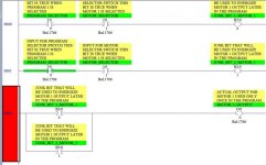
I am posting a example below for you to see.
This example is also a small clue for you to help structure your program.

BCS

B3 MUL OUTPUT.jpg
 
Last edited:
First thing I notice is you do not need 2 start stop buttons. Your selector switch is making the decision on who goes first. So I would use my start/stop buttons to turn system on. Then hold on by Selector Switch conditions.
 
First thing I notice is you do not need 2 start stop buttons.
Remember this is a student problem. You don't get credit for stating what you need or don't need, only for using the equipment listed. Think of it as a project where the customer has certain equipment that MUST be used. So use the two N.C. STOP and N.O. Start PBs in parallel combinations for each motor.

Even though a selector switch only has 1 physical contact, that contact can be used in the PLC program as many times as needed (probably one lesson this lab is supposed to teach).
 
Lancie, I did not see the link he posted showing his program. Plus I banged it out before leaving to a job site. I also took the view of listed inputs and thought he had 10 inputs, 2 outputs. 1 N.O. for each position on the selector switch. The OP said he had everything except the switching of the selector switch and I was trying to give him an idea of how to accomplish it by using conditional binary control bits in the holding circuit. To show you could add additional stop conditions in the holding circuit to accomplish the task.

Sanzen, Pay attention to Lancie he is a respected forum member and a retired Engineer with great patience and willingness to help students here on the forum. He is an expert with many programming platforms and you will do well with him as a tutor. As we all do.
 
Last edited:
Lancie, I did not see the link he posted showing his program.
I understand. Many students do not realize that we can't help much until they post the entire problem. He probably went back and added some details. As you know, answers based on only part of the problem has always resulted here in a partial answer!
I have everything to work save for having the selector switches killing the motors when either of the selector switches are flipped.
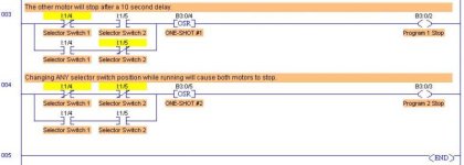
In that case, here is a way to use the selector switches to produce the "Program 1" and Program 2" bits mentioned by your instructor in his hints. Use OSRs so that these Program bits are only ON for 1 PLC scan. When either selector switch is moved, one of the 2 Program Stop bits will activate, regardless of the switch positions. That is enough to stop both motors.

Using your instructors guidelines, I was able to get the program working in 5 rungs using LogixPro. The first 2 rungs are the motor outputs, 3rd rung is the Selector Switch #1 Stop, and the Timed Delay Stops. The last 2 rungs are in the picture posted.

I used the required Inputs (2 Stop PBs, 2 Start PBs, 2 Selector Switches with 1 physical contact each, 2 Motor Overload Contacts, and 2 Motor Outputs). I also used 4 binary bits instead of 5 as he suggested, and 2 OSR One-Shots. I did use 2 timers, both On Delay types instead of his suggested 1 On Delay and 1 Off Delay. To use the Off Delay, your logic would need to be different than mine. (I understand that the hints are not requirements as is the first list).

Motor Stop with Selectors & Timers- Rungs 3 & 4.jpg
 
Last edited:
I see now that I only did the 6B part (did not scroll my screen UP to see 6A), although 6B covers everthing except only starting one motor at a time and the start delay.
 
Last edited:

Similar Topics

Hey guys, Our Powerflex VFD table is really close to the keyence light curtain. We are using AB PLC it isnt a safety PLC. Our VFD is hardwired...
Replies
5
Views
2,296
Hello guys, I am currently looking through some examples of how timers work, but this ladder logic diagram gets me really confused. Once I:1/0 is...
Replies
2
Views
1,860
Can anyone help with this in Automation Direct Directsoft 6. I am trying to use an input X1 as a busy signal. When X1 comes on I want to have a...
Replies
5
Views
1,793
I browsed the forums a bit but couldn't find an exact response to this issue. In most cases people seemed to recommend using TON timers instead...
Replies
9
Views
3,018
I want to use a 1 minute off delay timer. Can some show a programming example. It is for a l32e compact plc
Replies
3
Views
1,488
Back
Top Bottom