one more PICO question

Sorry Ron, I have to agree with 93 on all 3 points he mentioned. I disagee with the "I would have 2 seperate transformers" statement though. Most of the panels I build operate on 480 or 240V (or 208V) single/three phase, and I have NEVER added a 1:1 transformer for the 480 or 240V loads. Sure there's a transformer for the 120V stuff, with one leg grounded. I use this to power the PLC, 24VDC power supply, and whatever else happens to need 120V. If my line voltage was 480V and I needed 240V in addition to my 120V, I'd use a 480 to 120/240V center-tapped transformer and ground the center tap. I can't think of an instance where I have ever (purposely) grounded one leg of a 240V secondary off a single-phase transformer.

I think Vic has provided the best reasoning why the PICO is rated for 240V use. Notice that L2 is also the 'common' for the AC inputs. Looks like they were just trying to save on the number of terminals needed. Notice the lack of a gounding terminal as well... :rolleyes:

Since I always use 120V to power my PLCs, I wouldn't run into this 'L2 must be grounded problem', but I've seen plenty of (US built) equipment where the PLC was powered by the 240V (ungrounded) supply. Many panel designers might skip adding a transformer if it's only purpose was to provide 120V for a PLC that can operate on 240V.

Then again, the PICO is not a PLC!... :D

beerchug

-Eric
 
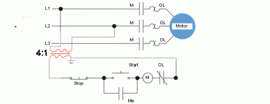
consider this modification to the circuit previously posted. Add the transformer fed from the line but transformed to 120 VAC. Now all your control circuit is 120...

stopstartmotor.gif
 
This is one of the subjects I've pondered.

RSdoran- I have seen those drawings in the older books. As for the time reference question... I am talking about current control systems.

I should have mentioned in my first post, "Assuming the power source is 480V"

Eric- I think we have 2 different types of machines in mind.
Really, if you think about it, What "device" needs 240V, that you can't get a 120V version?

Eric Nelson said:
If my line voltage was 480V and I needed 240V in addition to my 120V, I'd use a 480 to 120/240V center-tapped transformer and ground the center tap. I can't think of an instance where I have ever (purposely) grounded one leg of a 240V secondary off a single-phase transformer.

If you did have some 120V devices and some 240V devices in the same system, and you only used one center tap grounded control transformer, think of the troubleshooting havoc you would have to deal with.

If you were going to use 240V solenoids, they would have 120V on them when off and 240V when on (reference to ground). Imagine: output is off, yet there is 120V at the terminal.

I believe that in most cases this would provoke some 3AM wake-up calls from the maintenance guys saying "all the outputs are stuck on".
 
Good 'modification' 93, we don't want to kill off any newbies... :eek:

I understand what you're saying. I guess I gave a poor '240V devices' example. I can't say I have ever needed to actaully USE that center-tapped transformer idea, so I didn't think it through. In any case, if there are 240V devices, then BOTH ungrounded legs would get fused and/or switched.

That brings up a good point about your '240V secondary transformer with one leg grounded' idea. The main reason I use 120V is BECAUSE one leg is grounded. Therefore, I only have to fuse, switch, etc. the ungrounded leg. When I have a few 240V single-phase devices, I feel like I 'waste' a lot of space with 2-pole breakers, 2-pole relays, etc.

It might actually make more sense to have a 240V grounded circuit in some instances. Smaller transformer, smaller wire gauge, etc.

IOW, 'Europeanize' my panels... :p

beerchug

-Eric
 
Re: Here's a revision on best49erfan's modifications

93lt1 said:
Here is a modification to make the drawing correct. :D

(I think I'll stick to drawing with Autocad) :D

Sorry for the double post. I wish I knew/had autocad. You see how bad my XFMR looks!
 
Eric-

This whole conversation has been from my "personal" point of view. I wasn't saying you are wrong. I was attempting to justify why I would use 2 seperate transformers.

How many 240V control (not power) devices have you come across that you couldn't order a 120V version?

A lot of the equipment I work with is my responsiblity, so when maintenance can't get it going, I get the call. I make sure that when equipment comes in the door (usually before that) there are no "strange" things in the control system. We try to keep everything somewhat standardized so the troubleshooter can start working as quickly as possible. I wouldn't want those guys to have to go dig out the prints every time they start a "breakdown call" just to find out what voltage each device is. In our machines red is typically 120VAC control and blue is generally 24VDC control wiring. Any 240VAC or 480VAC is typically power wiring and is black.
 
we somewhat follow that wire color coding. red for 120, blue for 24v dc, black is most of the I/O wiring and yellow for anything that is powered externally from the panel so you know if you kill the panel, there is still some power in it.
 
ok. I just wired up my test circuit. A 9V battery for output power and a led to show that the output is working. I whenever the ouput is off, the led is on. Why is this?
 
I've developed the following for use in my panels;

Black is anything higher than 120VAC
Red for 120VAC
White for Neutral
Blue for 24VDC Positive side
Blue with White Strpe for 24VDC Negative Side
Blue with Black stripe for all 24VDC I/O.
Almost never use 120 VAC I/O.
And of course the yellow for outside power.
 
best49erfan said:
ok. I just wired up my test circuit. A 9V battery for output power and a led to show that the output is working. I whenever the ouput is off, the led is on. Why is this?

Since the Pico only has relay outputs, it sounds like you have the battery, output, and LED wired in parallel. When the relay is open, the LED lights, but when it closes, it shorts out the battery. No voltage = no light. Expect to have a dead battery soon... šŸ™ƒ

They should be connected in series.

BATTERY(+) to one side of the PLC output
Other side of PLC output to LED(+)
LED(-) to BATTERY(-)

Be glad you used a battery for your test. A 9V probably doesn't have enough current to damage the relay output.. (n)

beerchug

-Eric
 
From a power standpoint it is correct that for there to be a voltage to ground the system , at some point , must be connected to ground. I see it all the time that an electrician will check fuses on a 480 volt delta 3 wire system trying to read each leg to ground. You will get anything from 0v to the total volts applied. The only reason you read 120 volt on one leg to ground and 0 on the other is because one of the legs is directly connected to ground. The fact that you read 60 v on one leg and 60 on another at any given time is not relevent. All that matters on a non grounded secondary is what is the voltage between legs.

It blew my mind the first time we set up a control panel for overseas and the customer specifically asked for 220v 50 hz control with one leg reading 220 v to ground. All we had to do was connect one leg of the CPT to ground and walah, 220v on L1 to ground and 0v on L2 to ground. Of course the important thing is what the voltage between the two legs suppling the control circuit is. Try running a control scenario with only one side of the control voltage hooked up.

The Pico unit , which was the original question, does indeed have non-volatile memory. This means , as you found out, that it will not loose its program during normal operating conditions or even when power is removed. We use the memory module as a back up on location. We simply dump program into chip and ship it with LCP. If customer ever has problem with unit and has to replace smart relay they can simply plug mod in and download program.
 
Im not with stupid.....I am stupid!

Eric Nelson said:


Since the Pico only has relay outputs, it sounds like you have the battery, output, and LED wired in parallel. When the relay is open, the LED lights, but when it closes, it shorts out the battery. No voltage = no light. Expect to have a dead battery soon... šŸ™ƒ

They should be connected in series.

BATTERY(+) to one side of the PLC output
Other side of PLC output to LED(+)
LED(-) to BATTERY(-)

Be glad you used a battery for your test. A 9V probably doesn't have enough current to damage the relay output.. (n)

beerchug

-Eric

Dude, you are right. How sad, I did all the 120v right, but fudged the DC side. Too damn funny if you ask me. I wonder what I was thinking. It was around midnight when I was doing it. My wife wanted to see what the thing could do since it had been laying around on my desk..... Will fix when I get home...........
 

Similar Topics

Hello, i need to use P_Intlk and feed the Status interlock OK bit to a P_DOut block. However, there's 17 interlocks for this output. How can I...
Replies
1
Views
117
Hi everyone, recently i worked with a cmore panel and have the question that how can clear alarm list whit remote form,right now only can with...
Replies
0
Views
114
Hello, friends, I am trying to upgrade a system that uses an Onrom incremental encoder (E6B2-CWZ6C) connected to a Danfoss VFD (FC360), but now...
Replies
4
Views
280
Hello Friends I have took the sample program from AB webpage and modified, but I can only send 127 chars...
Replies
1
Views
191
Hello, I am new here and have been working with PLCs for a few years now. I have been tasked with setting up a Micrologix 1400ā€¦.. to a Cmore 10...
Replies
10
Views
510
Back
Top Bottom