PIDE Autotuning for Level Control

WHY IS A PID NECESSARY?

A person uses PID auto-tune, therefore he cannot write a closed-loop equation, therefore he cannot know that the closed-loop integrator with a proportional in the feedback is a first-order lag (the gain on the SP channel is 1, and on the disturbance channel 1/kp ), hence personuses PID autotune...
Am I the only one who thinks that asking questions to which the answer is obvious is, shall we say, an ineffective exercise?

The above answers the question "Why is PID used?" or in other words, “why does the OP think that PID is necessary?”

If you need to answer the question “is PI necessary or P-only is enough?”
We do not have sufficient information to answer this question (volumes, flows, actuator velocity, level deadband)

But in any case, all this does not matter at all, because the OP asked "Why doesn't PIDE autotune work?"

DrBitboy, I already suggested that you teach people the alphabet.
I think it makes sense for you to create a topic in which you will teach people to read (for example, manuals and what other participants write) and write (formulate questions, describe experiments done, give excerpts from documents). Thinking that it would be more time efficient to teach it in one topic instead of teaching it in every topic.

If you want to get complicated, then see this.

Ugh!!! And I was already starting to afraid that we wouldn’t get a Peter’s-link at this topic.

Peter, do you wonder why it doesn’t make sense to write a book “How not to be a dumb”?
- Because a smart person knows this without reading this book
A dumb will not read the book or will not understand what is written in it.


Level control is simple.

My personal nightmare "PID-closedloop-tuning" was level.
 
Does anybody have any tips for PIDE autotuning for level control?
d'Oh! I forgot the most important questions:

  • What is the loop update time?
    • this also requires the other questions' answers that quantify the system (flowrates, vessel size and configuration, etc.).
  • How are you controlling the PIDE execution to enforce that loop update time?
 
d'Oh! I forgot the most important questions:

Just to broaden my horizons: how do these questions relate to PID autotuning?

If we are talking about manual PI controller tuning then:
ki=0, kd=0
increase kp until one of the following states is achieved:
- P-control achieves a result not exceeding the deadband, provided that the actuator is not “overloaded”
- P-control does not achieve the result or the actuator is “overloaded”

Case 2: very carefully increase ki (ki/s) / decrease Ti (1/Ti*s). If PIDE scaling is correct: ki<=0.1* kp. I.e. it is advisable to start with ki= kp*10^-4


P.S. Suppose, I'm not trustworthy
 
I am retired now , but looking into my old files I found this one.

This small tank was called Desaireator tank , it worked at 250 °C, that was the reason I did not use a radar. The whole thing was used for distilling palm oil.

I recalled this one worked perfectly for more than 10 years.

Level was read by a pressure device and oil entering the tank was driven by a valve and pump or by a vfd pump.

Oil going out of this tank was controlled by another PIDE with flowmeter and vfd pump.

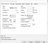
PIDE Level TQ_Desaireador.jpg
 
Wow, I admire you. You must not have any sisters.

Nevertheless, I appreciated your video. I have much to learn about PID systems.

Have 3. None of them came with an open loop transfer function and system identification doesn't work. They don't like being measured.

BTW, the gain of a tank is 1/surface_area of the tank assuming the pumps response is fast enough. The integrator time constant should be chosen so that disturbances are brought back to 0 error in 5 integrator time constants.

so if the pump pumps 1 cubic meter per minute and the surface area of the tank is 10 square meter the level will change by 0.1 meter/min. If the pump has a gain of (10 (m^3)/min)/100% then 10% control will result in the 0.1 meter/min level change assuming nothing else is adding or subtract fluid.

The open loop transfer function for the pump and tank is Kpump/(area*s). It is easy to calculate gains. From here. No autotuning is required.

There are non-integrating and integrating systems. They can have one two or more open loop poles. If there are two poles, then they can be complex.
Each one of these different combinations requires it's own basic model to fit the data to. An auto tuner could try all of them then chose the one with the best fit. Most do not do this. Most PLCs are setup for FOPDT or SOPDT systems if any.
 
d'Oh! I forgot the most important questions:

  • What is the loop update time?
    • this also requires the other questions' answers that quantify the system (flowrates, vessel size and configuration, etc.).
  • How are you controlling the PIDE execution to enforce that loop update time?
@Maxk wrote
Just to broaden my horizons: how do these questions relate to PID autotuning?
Choosing a loop update time and ensuring the PID instruction executes once per loop update time are the most critical tasks involved in configuring a PID instruction; they are also the tasks that are most often done incorrectly.

@Amarks95: there are a few open questions, specifically post #s 9 and 17, that need answers in order to address the original query about autotuning.

TL;DR

The autotune configuration has an option for the user to select the process model (e.g. level; non-integrating; etc.) and other parameters (e.g. step size for CV), and then the autotune algorithm will

  • change the CV,
  • collect PV data that change over time in response to that CV change,
  • fit those PV data to the chosen model,
  • and finally calculate and present tuning parameters based on the chosen model fit.
The user-specified PID loop update time, along with whatever scheme is implemented in the PLC program to execute the PID loop exactly once per update time, contribute to the quality of the collected PV data. For example, if the tank's cross sectional area is large compared to the flowrate change triggered by the change in CV, and if the loop update time is small and/or the number of PID loop updates used by autotune to collect the PV data is too few, then the level might not move enough to get useful PV data, or the level change may have a signal-to-noise ratio that is too low to generate a good fit to the process model.

Also, in Post #1, there was a qualitative statement that the autotune algorithm "didn't product good results." It would be useful to quantify that statement: what about the results was not "good;" was the response too slow; did the autotuned system oscillate too much; etc.?
 

Similar Topics

Hi! I'm trying to understand how does work the PIDE autotuning feature and I've got good documented resources for it from the Rockwell library...
Replies
8
Views
13,275
Greetings ... someone sent me a request for some student handsouts that I developed ... turns out that I had this hosted on my business website...
Replies
0
Views
134
Studio 5000 version 34. Have error on PIDE CVFaulted (Status1.2), Control variable (CV) health bad. No more information online or in...
Replies
3
Views
973
Hi everyone, I am trying to add a control loop to my HMI interface however I keep getting the following issue, any idea why this would happen?
Replies
8
Views
1,618
We have a routine that we trigger with a JSR every 10 seconds that has PIDE instructions. This resides in a Periodic task that triggers every...
Replies
6
Views
926
Back
Top Bottom