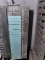
PLC not following program set

Yes I see the rothy boxes are the amount of spindles that spinning


I am in South Jersey how I can find someone to look at it ?

Ask one of your local electrical distributors if they have someone to recommend. Per Steve's post, there are some areas to measure. But if more than one spindle is exhibiting this behavior, I'd look for common voltage sources. That's the 24vdc supply to Tha analog modules, or the 230vac supply to the Rothy drives. Start there and see if you have 24vdc and 230vac.
 
Couple of points here....

  • The PLC won't change it's programming, at all, ever. Rule that out.
  • The drives are being told what to run either by an analog or digital or no signal at all.
  • you can help determine what this could be by explaining how you set the speed on the drives. Do you just tell it to run and then it goes? do the drives change their speeds on their own normally during operation? how many speeds does it run?
  • picture or information on the drives wiring terminals would be helpful if you can't determine the control yourself.

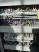
If this has an analog signal out, then I could see it being a bad connection going to the drives or a failed/bad analog output, I can't tell from the picture what IO it has.

If these are all controlled speed on presets speeds then I could also see this being caused by a bad output or an output not turning on for a speed select and it's causing them to default back to a different speed.

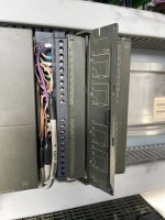
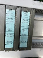
From my earlier post, they are 5HD01 modules which are 4 channel analog outputs. Pretty sure that corresponds to the 8 spindle drives, although OP hasn't confirmed. The fact that multiple drives are exhibiting this behavior points to a common voltage supply issue, or possibly a bad analog module if only half are doing this.
 
From my earlier post, they are 5HD01 modules which are 4 channel analog outputs. Pretty sure that corresponds to the 8 spindle drives, although OP hasn't confirmed. The fact that multiple drives are exhibiting this behavior points to a common voltage supply issue, or possibly a bad analog module if only half are doing this.
True, I did not see his pictures on the second page. the new forum layout is messing with my head!

I think OP's best bet at this point is to hire someone in to help.
 
Couple of points here....

  • The PLC won't change it's programming, at all, ever. Rule that out.
  • The drives are being told what to run either by an analog or digital or no signal at all.
  • you can help determine what this could be by explaining how you set the speed on the drives. Do you just tell it to run and then it goes? do the drives change their speeds on their own normally during operation? how many speeds does it run?
  • picture or information on the drives wiring terminals would be helpful if you can't determine the control yourself.

If this has an analog signal out, then I could see it being a bad connection going to the drives or a failed/bad analog output, I can't tell from the picture what IO it has.

If these are all controlled speed on presets speeds then I could also see this being caused by a bad output or an output not turning on for a speed select and it's causing them to default back to a different speed.
We do have an electronics. Guy but he keeps suggesting the PLC which I know it is not

What can I tell him to test exactly please ? And where and hopefully I can guide him
 

Attachments

  • IMG_2044.jpeg
    IMG_2044.jpeg
    148.1 KB · Views: 15
  • IMG_2045.jpeg
    IMG_2045.jpeg
    162.3 KB · Views: 15
  • IMG_2035.jpeg
    IMG_2035.jpeg
    260.4 KB · Views: 15
Can you set every spindle to the same speed as a test? If so, have your tech measure the DC voltage from the drive to the motor at X3 13 and 14. Then have them check the DC voltage at 4 and 5.

The motor voltage should be the same for all 8 if running the same speed and the analog voltage on 4 and 5 should be the same from the PLC.

That's assuming each spindle doesn't have a different gearbox with different ratios.
 
This is what you are referring to


It would be here ? And do I have to ground it somewhere?

If I have to myself

image.jpgimage.jpg
 

Attachments

  • image.jpg
    image.jpg
    200.1 KB · Views: 1
Can you set every spindle to the same speed as a test? If so, have your tech measure the DC voltage from the drive to the motor at X3 13 and 14. Then have them check the DC voltage at 4 and 5.

The motor voltage should be the same for all 8 if running the same speed and the analog voltage on 4 and 5 should be the same from the PLC.

That's assuming each spindle doesn't have a different gearbox with different ratios.
I can set I see no lights lighting up ?

if that’s normal ?

while they are spinning
 

Attachments

  • image.jpg
    image.jpg
    183.5 KB · Views: 3
Regarding robertmee's suggestion:
When you set all spindles to the same speed you should measure the same voltage across terminals X2.4 and X2.5 on each 806X7 drive. If you don't read the same voltage, there is something wrong with the analog output signals on the ones that show a substantially lower voltage than the rest.
If they all show the same voltage (or close to the same), check the voltage across terminals X3.14 and X3.15 on each 806X7 drive. They should all show the same voltage. If they don't there is something wrong with the 806X7 drive(s) that show substantially lower voltage.
If the analog speed reference signals (X2.5 - X2.5) and the armature voltage levels (X3.14 - X3.15) are all the same, there is a problem with the motors for the spindles that are substantially slower. It could be a mechanical problem in that the motors can't reach the speed they're being told to run because they can't produce enough torque to drive the load. It could be slippage between the motor and the load.
 
I can set I see no lights lighting up ?

if that’s normal ?

while they are spinning

The analog module SF LEDs indicate fault...they would be on and Red if your supply voltage was faulted or if you had a channel fault (short circuit). I happen to be a site today that has one operational..no lights is normal.
 

Attachments

  • 20240226_161009.jpg
    20240226_161009.jpg
    115 KB · Views: 6
At this point, please measure the voltages I and Steve have described. Can't go much further without that test.
 
At this point, please measure the voltages I and Steve have described. Can't go much further without that test.
Ok thanks again for your time and knowledge

One final question can the encoder go bad in the PLC and cause that spindle not following the HMI program?

It is an older PLC s7-300
 
Ok thanks again for your time and knowledge

One final question can the encoder go bad in the PLC and cause that spindle not following the HMI program?

It is an older PLC s7-300
What encoder? I see no encoder connections to your PLC. From what I see, this system is open loop. You set an RPM setpoint, the PLC converts that to a 0-10V signal that's sent to the Rothy Drives. The Drives convert incoming 230VAC to a DC voltage to run the motor in proportion to the 0-10V signal coming from the PLC.
 
What encoder? I see no encoder connections to your PLC. From what I see, this system is open loop. You set an RPM setpoint, the PLC converts that to a 0-10V signal that's sent to the Rothy Drives. The Drives convert incoming 230VAC to a DC voltage to run the motor in proportion to the 0-10V signal coming from the PLC.
Ok thank you very much trying to get our electronics guy to come look at it , he just keeps saying it’s from Germany and just seems like doesn’t know what to look for


I appreciate that guidance I wish I knew how to test it myself with multimeter or I would by now
 

Similar Topics

The past week we received a new piece of equipment from Germany which utilizes siemens controls. Typically in our company we use A.B. controls for...
Replies
9
Views
182
the conveyor can stop because of a safety sensor or safety switch. And also it can stop because of an object jam detector sensor. If the conveyor...
Replies
5
Views
186
Good Day to all of you, this is my first post, i will try to explain as best as possible, english is not my natural language. I am performing an...
Replies
0
Views
40
Hi All, Someone at work has put a PLC system on my desk, that's just been taken off an idle production line. He said "It's an S7 PLC. We don't...
Replies
10
Views
249
I have a project to automate four generator sets. The system will monitor and store the load demand of the factory. Once there's Power outage, the...
Replies
0
Views
64
Back
Top Bottom