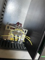
Steve Bailey outlined it pretty well, calling out the exact terminal numbers on the Drive to measure. That's the only place you need to measure as that holds both the PLC signal 0-10V and the Ouput voltage to the DC Drive. Again, if possible, run multiple spindles at the same speed and have your tech measure:Ok thank you very much trying to get our electronics guy to come look at it , he just keeps saying it’s from Germany and just seems like doesn’t know what to look for
I appreciate that guidance I wish I knew how to test it myself with multimeter or I would by now
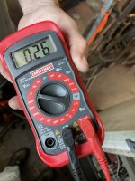
Incoming AC Voltage to each drive (should be 230VAC)
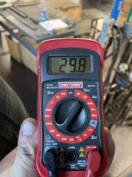
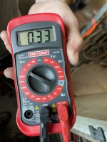
Incoming Analog 0-10VDC signal from PLC. Could be anywhere between 0 and 10V, but should be consistent across drives if running same speed
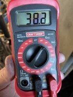
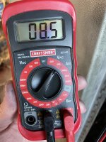
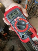
Outgoing DC Voltage from Drive to Motor. Could be anywhere from likely 0 to 90VDC, but should be the same across drives
Then when you do a speed change, both the Incoming Analog voltage and the DC Voltage out to the motor should change somewhat proportionally to your new speed.