Please Help-Another Turret controlled by PLC

The solenoid should go low when the turret locks. After the CCW motion. Its staying energized.


My Rung 10 will leave the [4 Indexing Solenoid Y001] output's value a 1 (energized), but then it should be de-energized when BOTH the brake engages (Y002 becomes 0) AND the Post-CCW timer (Time delay "T2" in the manual) expires.
 
Last edited:
It is 1 number off though. for instance if I call tool 7 it stops at tool 8. If i call 2 it stops on 3


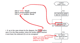
The -]=[- compare of DS2 and DS1 on your rung 12 should be changed to compare DS3 and DS1 instead. Then it will stop on the correct tool.


(update: add image, from manual, below).


xxx.png
 
Last edited:
Alright so most of my self inflicted quirks are worked out of it lol. Only thing now is the brake still didnt turn off when the Lock signal went high. Everything else seems good.
 
Alright so most of my self inflicted quirks are worked out of it lol. Only thing now is the brake still didnt turn off when the Lock signal went high. Everything else seems good.


The brake should stay released (output Y002 value = 1) until the Post-CCW Timer [T2] expires, and the brake should be applied (Y002 value = 0) after that. I don't think the brake should be released again when [Turret Locked X006] becomes 1.

Is X006 the same as (6) Locking Control Switch on page 16 of the manual?
yes its x006.

The motor Brake holds the position. So as soon as the X006 goes high the Brake signal should go low. Holding that Locked position. Otherwise as soon as the motor CCW turns off the spring pressure unlocks the turret.
 
Last edited:
yes its x006.

The motor Brake holds the position. So as soon as the X006 goes high the Brake signal should go low. Holding that Locked position. Otherwise as soon as the motor CCW turns off the spring pressure unlocks the turret.


Okay, then it is probably the (5) Indexing Control Switch that is keeping the brake released (keeping Y002 value = 1); remove* X005 from the logic of the rung that controls the brake (rung 15 in the last PDF you posted), and the brake should be applied (Y002 value changed to 0) as soon as the CCW motor stops.

I put X005 in there as belt and suspenders i.e. to ensure the brake would stay released between the CW Motor stopping and the T1 timer starting, but it should work without X005.

* An alternative would be to replace that [NO X005] with a [Falling Edge Y004 Motor CCW], to ensure the brake does not release for at least one scan beyond the time when the CCW motion is stopped; the T1 timer should keep the brake released after that.

That said, the (4) Indexing Solenoid should have been staying on until the T2 timer expired; T2 starts when CCW motion stops (i.e. when Turret Locked becomes 1), and should have held the solenoid (against the spring?) for 50ms after Turret Locked in my code, and for 3s after Turret Locked in your code.
 
Last edited:
That did it. Man I cant thank you enough. Everything seems to be working like it should now. I'm going to put power to everything and check.
 
I cycled power to the ESS and the plc. When the plc boots it turns on Y2 and Y3 until it faults out. Whats the best way to prevent this from happening?
So the PLC didn't store the value of DS1. The mach4 program that controls the machine stores the value of the current tool but the PLC writes ds1 to 0. Can i set ds1 to ds2 when it boots on? Just so CW doesn't trigger as soon as it sees power?
 
Last edited:
Or should i just do an edge contact for T3 which is the runtime timer, and put that on the CW rung? B/c the value of ds1 doesn't matter until a tool change is called.
 
[Update: never mind all that malarkey; SC2 is the system _1ST_SCAN bit]


Code:
     _1ST_PASS
        SC2
 --------] [-----------[Copy DS2 to DS1]----
 
Last edited:
Well that's easy enough. I'm going to do some testing to make sure I can recover after I estop in the middle of a tool change and all that good stuff.
 
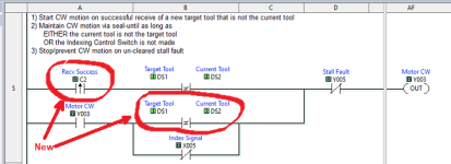
Whoopsie, I missed the obvious: never mind that _1ST_SCAN malarkey; we can instead simply add (AND) a single rising edge of [C2 Recv Success] as a permissive to (with) the start condition for clockwise motion; that will prevent the motor from starting on recovery from a power cycle.

It will also require adding a [DS1-|≠|-DS2] to the seal-in for CW motion; see below and attached.

However, note that there is, and has been all along, a possible anomalous edge case: if the current tool is the target tool, but the lock failed, then you will need to send a command to move to any different tool, followed by a re-send of the target tool, to jog it around again.

xxx.png
 
Last edited:
I will implement those now. I was having a few issues last night, the CCW was going high before CW. I solved that issue though. I will try it as soon as i get this uploaded to the PLC.

I'm also having trouble controlling X8 with modbus as well as reading y005 when there is a fault. Is it possible to read and write to coils without having physical wires present? or do i need to run those wires to the correct pins?

Or what would be the better way? Hard wire? I have 2 inputs(X007-X008) and 2 outputs(y005 y006) that are not being used. I need a fault signal(which currently is y005). I need a start tool change signal-Tool change finished(which is X008). Then I need a Fault reset which is X007 currently. Or could i read and write to C numbers? The fault signal will need to go both ways. Meaning if there is an e stop condition in the machine i need to fault the Turret. Then if there is a Turret fault during a tool change i need it to send a signal to the machine telling it there is a fault state.
 
Last edited:

Similar Topics

I've got a DH+ Network with 3 SLC 5/04's and 2 PV1000's. 1 of the SLC's is being used solely as my PC Interface - I'm doing a DF1 Pass-Thru on it...
Replies
19
Views
9,166
please help me . I have to make this ladder diagram and I can’t figure it out :(
Replies
12
Views
355
Hello, I am trying to get a Yokogawa Hart pressure Transmitter and a Rosemount Temp Transmitter to read on a 1769-IF4 module on an L33ERM...
Replies
10
Views
379
Please help me, I have solve many week but still not solve it. I found trouble of factory talk studio when I set tag by browse address of OPC...
Replies
0
Views
124
Back
Top Bottom