Problem for PowerFlex700

angi

Member
Join Date
Jan 2010
Location
us
Posts
361
Hi guys

I got a problem for PF700, we got some PF700 on the floor, they are all run by same program, and controlled by devicenet(20comm-D), but one of them could not be started because of stop asserted, we could not find out where the stop signal comes from. how to fix it?

Thanks
 
Hi guys

I got a problem for PF700, we got some PF700 on the floor, they are all run by same program, and controlled by devicenet(20comm-D), but one of them could not be started because of stop asserted, we could not find out where the stop signal comes from. how to fix it?

Thanks

Presuming that you can communicate with Drive Executive, have you checked the programming for the inputs? See if any of them are programmed to be a inhibit or stop.

That said if you cannot see what DI 6 is programmed for then it is "hard programmed" via the "hardware enable" jumper. (J10)
 
I'm guessing you start and stop the drive remotely via Devicenet? If so, there may also be a hardwired circuit connected to an ENABLE or STOP input (the STOP inputs is usually OFF for stop).

I would check if there are wires connected to the digital I/O. You may be missing an input.... :confused:

🍻

-Eric
 
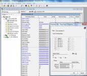
The PowerFlex has a monitoring parameter named "Stop Owner".

When the drive is in the "Stop Asserted" mode, the Stop Owner parameter indicates which DPI Adapter is asserting the Stop command.

Frequently the culprit is the discrete Terminal Block.
 
From the stop owner parameter, we know that the stop signal was from Input1, but we did not wire anything there. how to understand it?
 
Digital input one (terminal point 27) is programmed by default to be the stop input. You must apply a signal to that input or change the associated parameter to "Not Used".

Remember, a stop input needs to be true to allow the VFD to run. Think of it as a "Not Stop" input...stop signals are intended to be fail safe. If there's a wire breakage you want the VFD to stop, so stop buttons are wired normally closed, and VFD stop inputs expect a signal to be present in order to allow the drive to run.
 
Stop Asserted Drive Alarms

A stop asserted alarm indicates that your drive is being directed to stop. Stop asserted drive alarms typically appear because one of the following rules concerning parameter configuration and wiring was not obeyed:

  • Parameters 361 [Dig In1 Sel] and 362 [Dig In1 Sel] must be disabled (choose the “not used” option) if the drive is not controlled with digital inputs such as push buttons.
  • If the digital input is powered by an internal power supply, then TB24 must be wired through a normally closed stop button going to the TB25.
  • If the digital input is not powered by an internal power supply, then TB25 on the I/O terminal block must be wired to the external power supply (through a normally closed stop button).
 

Similar Topics

Hello, I need to write the following program in Ladder language, but I could not integrate the Fibonacci sequence into the ladder. Can you help...
Replies
22
Views
461
On all pages of my project i have a lot of information, texts and details that should not not be shown. I can remove them for each part apart from...
Replies
0
Views
51
Hi, I have had problem with upgrading some projects from v16 to v18. I tried it on 3 diffrent computers. I want to post this so that anyone that...
Replies
3
Views
213
Hi, I am having a challenge installing a new drive ACS355-03E-44A0-4 as it keeps on displaying Fault code F00018 even when the load is not...
Replies
3
Views
152
I have an issue on my vessel, we have water tight door system created in China, company is no longer operating. We have 7 doors each with their...
Replies
4
Views
165
Back
Top Bottom