Quickie Problem

Tom Jenkins said:
There is no way to tie two or three inputs to a single counter and insure an accurate count, unless you can insure that only one input at a time will be tripped AND insure that the first input has dropped out before the second is tripped! Remember, counters count off-to-on transitions. If one input is already on when the second trips, the counter will not see a transition and will not increment the count.

Huh?

That's not quite accurate, Tom. That's why I posted the timing diagram to show what has to happen with the counter. The one-scan-pulse of X2' is delayed (but only when X1 and X2 are active simultaneously) by 2 scans, in order for there to be a low-to-high-to-low transition from X1'.

I've got the code for two gates to one counter - it's not hard to expand it to three. I want to see what Waidesworld comes up with before I post my code.
 
Code

So my first line should be similar to
If X1 and X2 then TIMER1

I am sort of getting it but I am groggy on this Logic still. It's been a while for me.
 
Oh. This is a REAL, physical counter.

I had been assuming an internal PLC counter, with a display somewhere.

The pulse width will have to be longer than one scan to be sure the counter sees it. That is a problem. Not insurmountable, but the code I've got won't do it.


A_ONS A_DELAY
---| |-----------------------------------( )

GATE_A B_ONS B_DELAY A_WAS A_ONS
----| |----+---|/|---|/|---+---+---|/|---( )
| | |
| A_WAS | | A_WAS
+-----| |-------+ +---------( )


B_ONS B_DELAY
---| |-----------------------------------( )

GATE_B A_ONS A_DELAY B_WAS B_ONS
----| |----+---|/|---|/|---+---+---|/|---( )
| | |
| B_WAS | | B_WAS
+-----| |-------+ +---------( )

A_ONS Y
----| |---+------------------------------( )
|
B_ONS |
----| |---+


Timing Diagram:

_________________________________
| |
Gate A: ___| |_____
____________________________________
| |
Gate B: ___| |__

_
| |
A_ONS : ___| |_____________________________________
__________________________________
| |
A_WAS : ___| |____
_
| |
A_DELAY: ____| |___________________________________

_
| |
B_ONS : _______| |_________________________________
__________________________________
| |
B_WAS : ______| |___
_
| |
B_DELAY: ________| |_______________________________

_ _
| | | |
Y : __| |_| |_______________________________


Perhaps if the WAS and DELAY coils were changed to timers, this might work.
 
Last edited:
You could "one-shot" and lock out the inputs. After one of the inputs is tripped, increment the counter with a "one-shot" and at the same time, set a latch to disable that input in the logic. Then do not re-enable the input, or reset the latch for that input until some event occurs that ensures that the car has exited the sensing area--maybe an exit sensor. This method will ensure that there are no "double counts" by the same car. And, because of the one-shot, only way to miss an input would be if two cars pulled onto their respective sensors at the EXACT moment--And I mean the EXACT moment--within the same program scan (what?? 4 or 5 mS??). There are ways to examine for and correct this EXACT event, also. All three "one-shots" may input the same counter. You can make the PLC do darned near anything you want--it just depends on how bad you want it and your own imagination (and maybe a little push, shove, or idea from your friends)

Damn, I just read the post about the real hardware counter. That's not real hard to do. Just make sure, like everyone has said, no two counter inputs (PLC outpouts) are on at the same time, that the output pulse is long enough to trigger the counter, and that the time between output pulses is long enough so the counter can distinguish between two successive pulses. Use one PLC output for all three sensors. When you get a count, using the method above, set a latch for the purpose of cycling the output pulse. This latch should start a TOF1, then branch to unlatch itself. The TOF preset should be the pulse length. Put the TOF1.dn bit in a rung to turn on the output. On the off transition of the output, start another TOF2. The preset for this TOF2 will be the minimum time between pulses. Put the not done bit of this TOF2 in the rung that starts the first TOF1, along with the not output bit. Each car sensor should have it's own latch, TOF1 and unlatch. Then parallel the TOF1.dns to the output.

What this accomplishes is no concurrent outputs. And if the count output is active because of one sensor, and another sensor trips, the PLC waits until the first sensor output is complete, plus the dead TOF2 time, then cycles the output for the next. The latch is the key--it remembers that the sensor was tripped and doesn't forget until output is cycled for that specific occurance.
 
Last edited:
Allen: I stand by my statement. What you are implying is that you have a technique that insures two inputs will not be on simultaneously so the counter will see a separate off-to-on transition for each. I allowed for this in my statement.

Waide: Since this isn't a school project I'll give you additional help. Use a separate counter for each input. Then add the two counts, and display the result. Why are you resisting the simple solution?

Code:
    X1
----| |----------|CNT     CT1
                 |
    CT1          |K9999
----| |----------|
                 |


    X2
----| |----------|CNT     CT2
                 |
    CT2          |K9999
----| |----------|
                 |

 Always_On
    SP1
----| |-------+--|LD
              |  |CTA1
              |
              +--|ADD
              |  |CTA2
              |
              +--|OUT
                 |V2000

This will display the total count in V2000, which is what the supervisor has to read! Refer to page 5-39, 5-51, 5-58, and 5-79 in the DL-205 manual.
 
Tom:

You are right. In my code, GATE_B must remain 'on' for the duration of A_ONS and A_DELAY in order to be captured. Since the physical object (cars moving over pad) was significantly larger than PLC scan time, the logic I posted above would work.

It would not work for a high-speed conveyor line where an object might only be 'seen' for one or two scans.

But if I'm interpretting the problem correctly, there is a physical, Omron counter at one of the booths that counts pulses from the PLC, not a display. So what Waidesworld is trying to do is to send pulses to that counter for each car that enters. That's why he had Y-coils in his first post instead of a CNT block.

I agree that this is not the best approach and should be redesigned to have a display, but it's what he's got.
 
Clearing the air

Each lane has a electromechanical clock with a pulse loop. As the car passes over the loop a pulse is generated sending a 12V signal to the counter to increment by one.

At the main guard house I have available to me these same pulses by means of parallel wiring.

I am trying to get input from each lane to the PLC (x1-x3) and output to two electromechanical counters (one resettable, one non-resettable)

I am hoping to pay a visit there tomorrow but later if neccessary to install the system.

I am very appreciative of any and all help I am getting so far.
 
Waide, I think you are still looking at the problem with tunnel vision.

As I understand it, you have a separate "contact" for each gate. The contact is wired in parallel to a physical conter at each gate and to the input of a DL-05 PLC.

You are trying to use the outputs of the PLC to trip another external counter for a total count. You will still have the same problem, since physical counters also count off-to-on transitions at their input. You will need some elaborate internal logic along the lines Allen is suggesting to avoid simultaneous closures of the PLC output and thus to make sure you count all gates properly.

For $177.00 you can get a DV1000 and cable from AutomationDirect.com. You can set it up and display the total count for less money than your trip to the site will cost, and your customer will be happy. It will display four lines at once - the individual counts plus the total, for example.
 
Tom

I was trying to work with the tools I have as opposed to tunnel my way thru' it. No offence to you sir, you have been a great help so far.
I was trying to work thru' it but obviously there is a solid brick wall in the way.

I explained my problem to AutomationDirect and this is the unit they told me that would suffice.

Time for customer service to receive a call....
 
Waidesworld:

It isn't the PLC that is limited. The most expensive, souped-up PLC in the world would still have the same limitation.

The problem is that you are using a counter at the guardhouse when you should be using a display. The counter needs to see a low-to-high-to-low clear signal in order to increment. While the code fragment I posted will give you that, it is limited in it's ability to handle certain circumstances.

The pulse width of both the WAS and DELAY, for both A and B must be increased to ensure that the counter gets a pulse that is distinguished from the next. But if the combined pulse is too long, it is theoretically possible for a car to go through gate C and not be recorded by the Master counter.

Perhaps Tom & I are being too picky. Does it matter if the count is off by a few? Will the rangers be saying "Oh-oh, 50,000 cars came in, but only 49,999 cars came out - there must be someone lost! Let's call Search & Rescue!"

Probably not.

But I think we've given you all the help we can on this. Good luck!
 
Missing Vehicles

Guys,
If a car is off every so often then nobody is going to cry murder. The whole policy is to make sure there isn't anyone making off with $10K in access fees every week or so.

I will try and incorporate your ladder logic and will definitely let you guys know the results,

Waidesworld
 
I have implemented the multi-input to one output external counter. I was looking to see if there was a more elegant software solution being proposed. I have the program ready but not tested. I'll attach it as a 'zip' file.
 
Not being sure of all the facts but let me see if I have this correct. There are a total of 3 gates each with its own counter but at the Main Gate you want to have a total count so the supervisor wouldnt have to goto all 3 gates etc to total the count. At the Main Gate you have parallel wiring from the other 2 gates.

1 Question to ask is "Is the Main Gate always open?" If so "Do you need individual counts for each gate. Technically this wont matter but can vary the way things are done.

What I was thinking is why not carry all the inputs for the gates to the plc. Then (if needed) increment the individual counter directly from a plc output? NOW comes the tricky part (for me but not most of y'all), why cant you setup an indexer (sequencer) type program that will increment the totalizing counter for any inputs from the 3 gates....ie queue the inputs until the output is free to pulse the counter. I hope I am explaining this right. This type of programming would take me awhile to develop because you have to use internal bits or words to setup the queue so you dont lose any inputs when triggered at approximate same time. The idea is to make sure the input pulse is detected and adds an output pulse to the sequence.

I think a Direct Logic is being used in this application. I would like to know if this would be a sensible approcach to this kind of an application. Wouldnt have to be gates at a parking lot, could be 3 conveyor lines merging onto 1 but needing product count from each line and total count off last line.
 
Ron -
I was thinking exactly the same thing. I see no reason it wouldn't work.
Take Tom's Car Count Total and compare it to a counter that is incremented each time you pulse your output (call it Output Pulse Counter ). If the Car Count Total is incremented (making Output pulse counter < Car count total ),pulse the output until the Output pulse counter = Car count total .

I think that would work.

Kevin Hammond
 
Ron and Kevin,

I think your is the correct solution. Yesterday night I've thought a similar solution, with a program working so:

1) The inputs from the three lanes are read and used to increment three partial counter, whose value is added to obtain the total car count

2) To solve the problem of the timing of pulses, two timers are set: the first has a preset of e.g. 0,5 s and the second of 0,1 s. The two timers are sincronized so as to have such a timing diagram:


  ____  ____  ____
_| || || | Timer 1
_ _ _
_| |___| |___| |__ Timer 2


3) Each time a pulse is emitted to trigger the mechanical counter, the number of emitted pulses is incremented (Emitted pulses = Emitted pulses + 1), and the number of pulses to be emitted is calculated as Remaining pulses = Total Car Count - Emitted Pulses".

If Remaining pulses > 0, at the next timer 2 timing interval a pulses will be emitted to the mechanical counter, decrementing Remaining pulses by one. And so on until all pulses will be emitted to the mechanical counter.

The timer 2 sinchronization permits to emit a train of pulses avoiding the risk of simultaneity of pulses.

Waide,

the next time you will propose a question to the forum, please describe clearly how the system is intended to work. It's very difficult to help you to let a system work if we don't know how the system is.

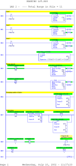
I attach a image of ladder I've drafted with RSLogix 500. Excuse me if there are some errors but I have not the time to review neither to test it: I must rebuild a huge Microstation piping model for tomorrow cause we have lost completely the last version of the file without the ghost of a backup.

Ciao, Luca

parking lot.png
 
Last edited:

Similar Topics

Does the Powerflex 40 At Reference status bit fluctuate or is it a solid at a given speed reference once the ramp completes (assuming no...
Replies
4
Views
4,490
Hi, I have a customer who has cleared a virus by completely reinstalling the PC. Now the problem is he has to reset his RSLinx license that I...
Replies
2
Views
2,061
Hi, can the Rades modem have a different IP range than the PLC/HMI's connected to it? I'm trying to connect to a customers site. The modem is...
Replies
10
Views
2,461
Hi I found this the other day and now for the life of me i cant seem to find it again!! Where do i find the FORCE command in GX while online ?
Replies
15
Views
4,951
Hi This is probably a question with a very simple answer but its late and I can't figure it out. If this is me being a complete buffoon then...
Replies
5
Views
2,310
Back
Top Bottom