Refrence table values how to set example needed

jcp

Member
Join Date
Feb 2010
Location
Multan
Posts
369
Hi friends;
Finally communication done. I am very thankful to Sir Steve and Russb which guide me through out the post.
I store the configration, programming logic but when store refrence table the message shown its empty and can not be store.
After go online see the logic which develop as under
%AI0001 input to the INT TO REAL block. Q is store in %R00001.
i see its read 32767. while in analog module configration i set following
ACTIVE CHANNEL=1
4 to 20 mA
Low limit=00000
High limit=+32000
Ref add=%AI0001
Ref ADD= %I0001
A guy say me you should also set the refrence table to get correct values mean hi and low limit.
I am unable to understand the refrence table values how to set?
Is there any example in which i read how to set the values? Then i start to develop the logic.
Regards
 
The "Reference Table" is the set of values all of the PLC's memory areas (%R, %M, %AI, %AQ, etc.) at any time. The message you got tells you that you have never uploaded reference table values from the PLC to the PC, so you have no values available to download. You do not need to do anything with reference tables before you start programming.
 
Hi;
For communication i short the cell in the plc (for a second) then its sucessful communication.
It means first i should store the ref table from PLC to PC.
Then restore to the PLC.
If PLc memory is clear and developer create the programme,configration and load to plc then what happen?
When i store the programme from PC to PLC i check
programme y
configration y
ref table y
but it send me message which i post.
When i am able to store ref table?
Second why the 32667 value shown in %R00001? while at that time transmitter at 4 mA.
sir is ther any example u send me in shape of article or image to programming the analog values and read out the EU values in the register. Thanking u i will remain
Regards
 
Don't worry about the reference table. Check "N" for the reference tbale before you download. Most of the data values in the reference tables are the result of the program. You don't need to manipulate them.

For communication i short the cell in the plc (for a second) then its sucessful communication.
I have no idea what what you did.
Please show a screen image of your logic. Logicmaster should show the contents of %R00001 at the "Q" node of the INT_TO_REAL instruction as a floating point number.
 
Hi;
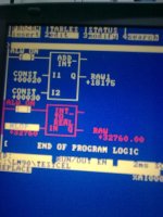
I attached image as steve suggest plz guide me what happen?
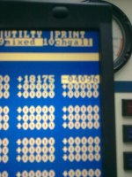
DTA0107 image shows the run time result. and DTA0108 picture of refrence table of %R0001 and 0002.
I am new with GE PLC programming.
after sucessfull communication i write a programme just check what happen and i am confuse to see result.
First i explain hardware specification
Rack 10 slots
Slot 0=power supply
slot 1= CPU352
Slot 2= CMM311
Slot 3= ALG223 Analog module 16 channel
slot 4= Digital input
slot 5= digital output
now i explain how i connect the transmitter with analog module.
Terminal 1= +24 VDC supply
Terminal 19= -ve or 0VDC
I get 24 on terminal 2 because manual of that module say its internal jumper for field devices.
So Terminal 2 connect to Transmitter +ve
Channel 1 that is terminal 3 connect to transmitter -ve.
I check the transmitter it gives me 4.13 mA.
In module setting only one channel active that is channel 1 select 4-20 mA low=+00000 and high=+32000
Now You guys see i add simple ADD_INT block just check i give 20 and 30 as constant at I1 and I2 respectively and result save in %R0002. I think it must be 50 but it shows 18175 why?
Second Transmitter gives me 4.13mA and i use INT_TO_REAL block it gives me 332760 why?
In the refrence table i see %R00001 shows -4096 and %r0002 shows same as addition result.
I am unable to understand what happen?
Plz guide me
Regards

DTA0107.jpg DTA0108.jpg
 
This PLC uses two consecutive %R addresses to store a 32-bit number. Your INT_TO_REAL instruction with %R0001 as the output stores the result of the conversion in the 32 bits spanning %R0001 and %R0002. The value you see on the screen is the result of the last time the address was written to. You will never see the value of 50 in %R0001 from the ADD_INT function because that value is immediately overwritten by the INT_TO_REAL instruction on the next rung. Change the output of the ADD_INT instruction to %R0003. In your reference table view, with the cursor on %R0001, press F4 (real) to display the value correctly.

As to why you are getting 32760 in %AI0001, the module is reporting what it sees at the terminal. I don't know the details of your transmitter, so I can't tell if you have wired it correctly. The wires are on the correct terminals for channel 1 of the module. Try reversing the wires at the transmitter.
 
Sir;
I use the rosemount 3351 smart transmitter. It have three terminals
1= +ve
2= -ve
3= Test
i connect the terminal 2 of module to terminal 1 of transmitter and channel 1(Terminal 3 of module) connects terminal 2 of transmitter.
am i right?
I connect the am meter in series with termianl 3 of module its read 4.13 mA. So its confirm that 4.13 mA is going to channel 1.
Secondly i give pressure to the transmitter the mA increses but no effect on count it still as shown in fig.
For the connection am i right? now what u suggest to me(Your student)
Regards
 
Have you tried reversing the signal wires? Have you tried a different channel on the analog module? Are you sure you have correctly identified the terminals on the ALG223 module? Odd numbered terminals are the back row. Even numbered terminals are toward the front.
 
Yes i am sure i connect on the right channel. And secondly i do not reverse the terminals at transmitter. Sir you meean i connect +24 to -ve of the transmitter and channel 1 connected to the transmitter +ve. is it correct u say?
i think transmitter may be damaged if i reverse the polarity.
am i right?
 
Maybe the channel on the analog module has been damaged. Try wiring the signal to a different channel. Make sure you enable that channel in configuration first.

I don't know anything about the transmitter you have, so I can't offer any advice about the conseqences of wiring it up backwards, but Rosemount is a well-respected name and their equipment has a reputation for being fairly robust. Since reversing polarity is a common mistake, I expect Rosemount engineers included protection against reversed polarity in the design of the unit. Unless something in the documentation for the transmitter clearly warns against reversing polarity I would be willing to accept the risk.
 

Similar Topics

Hi Experts, I am trying to understand the adressing of the Analog Inputs and Outputs in the module Slot 2 - IC693ALG442 I have here %AI0001...
Replies
15
Views
1,894
I just upgraded the firmware on a couple of our PowerFlex 525 in one of our machines. The upgrade was from 2.002 to 5.001. I also changed the...
Replies
4
Views
2,466
Hi friends; i used the %SC0014,%SA0003,%SA0014,%SC0010,SC0011, SA 0009. can i reset these bits by using as %SC0010...
Replies
12
Views
3,790
Hey folks. I want to know what does refrencing encoder mean. Does it mean we are resetting encoder? In our plant when there is a problem with...
Replies
10
Views
3,018
We have a new Yaskawa G7 Drive That we Give A refrence Via Profi bus of 100HZ but only runs up to 80 to 85 HZ. Max speed of the drive is 110 HZ...
Replies
10
Views
3,293
Back
Top Bottom