Rotation problem

I know I need additional rungs for stopping and reversing; however, I don't understand why the OSR SEEMS to be true on the low-to-high as well as the high-to-low. I am a little confused.

Thanks again
 
I am not sure what you have in your logic at this point. If you duplicated Alaric's logic exactlly, you should have a forward or reverse bit that comes on each scan. Do not worry about the state of the OSR bits. (The OSR bit is by definition an internal bit that is used by the PLC to store a temporary flag. However the logic downstream of the OSR will go ON for only scan, which you may not even see with the human eye.)

You need to study up on how the OSR works.

OSR [One Shot Rising]

Description
The OSR is a conditional input instruction that triggers an event to occur one time. Use the OSR when an event must start based on the change of state of the rung from false to true, as triggered by a pushbutton. An example would be to use the OSR to freeze rapidly displayed LED values.

Place the OSR on the rung immediately before the output instruction. Then reference the output as the one-shot in your program. The address that you give to the OSR input instruction is where the previous state of the rung is retained.

You must enter a bit address for the OSR. Use either a binary file or integer file address. The bit address you use must be unique. Do not use it elsewhere in the program.

The address assigned to the OSR instruction is not the one-shot address referenced by your program, nor does it indicate the state of the OSR instruction. This address allows the OSR instruction to remember its previous rung state.

Warning! Do not place input conditions after the OSR instruction in a rung when using a Fixed or SLC 5/01 controller. Unexpected operation may occur.

The SLC 5/02, 5/03, 5/04, 5/05 and MicroLogix controllers allow you to use one OSR instruction per output in a rung. With the Fixed and SLC 5/01 processors you can only use one OSR per rung, regardless of the number of outputs. OSRs cannot occur within branches when using the Fixed and 5/01 controllers.

Operation
When the rung conditions preceding the OSR instruction go from false-to-true, the OSR instruction is true for one scan. After one scan is complete, the OSR instruction becomes false, even if the rung conditions preceding it remain true. The OSR instruction becomes true again if the rung conditions preceding it transition from false-to-true.

Rockwell Software 2000
 
Last edited:
Every rung begins as TRUE

If an OSR is preceded by a TRUE state it looks at its storage bit, the address attached to the OSR.

If the storage bit is FALSE then it outputs a TRUE to its right and stores a TRUE into the storage bit. Now in your case, while it may possibly set the input table bit to TRUE that will get overwritten on the next scan by the state of the actual input.

If, instead, the storage bit is TRUE then the OSR outputs a FALSE to its right.

And, if the OSR is preceded by a FALSE it stores that to its storage bit and outputs a FALSE to its right. In your case this will never happen since the rung always begins as TRUE.

Now, let's see what happens as your input turns ON and OFF:

Input ON - the OSR outputs a FALSE to its right because its storage bit is TRUE.

Input OFF - the OSR outputs a TRUE ON EVERY SCAN because, even though it tried to store a TRUE to its storage bit on the previous scan the scanning of the input sets it back to FALSE.

So what you should be seeing in your 'For' and 'Rev' outputs is:

While Sensor B is ON neither output should be ON

While sensor B is OFF the outputs should follow the state of Sensor A.

So, place a contact of sensor B before the OSR and change the OSR reference to a spare 'B' register bit.

(By the way, your OSR construction would work in AutomationDirect since it processes this type of instruction differently)
 
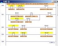
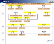
Here is Alaric's program running on the LogixPro simulator. It seems to work. If B is ON when A goes ON, then the Reverse output stays on. If B is OFF when A goes ON, the the Forward output stays on. When a change in direction occurs, the Forward & Reverse swap states upon the next scan.

attachment.php

attachment.php


BOTHS SENSOR A  AND B ON AT SAME TIME.jpg SENSOR A  ON- B OFF.jpg
 
Last edited:
YES SUCCESS

Thanks to everyone who helped me out. I think my problem was that I didn't have a complete understanding how the |OSR| actually worked. The program that Alaric submitted did work and was the key to helping me understand. Thanks again everyone.


Scott
 

Similar Topics

Hello everyone. I am trying to figure out what the best way to control three pumps would be. I have searched the forums and cannot seem to find...
Replies
11
Views
2,304
Hello all, I am working on a project in FactoryTalk SE. Suddenly while working on a new screen, the global objects I am copying to it are not...
Replies
0
Views
1,273
Good evening once again everyone, I have a Lenze ESV222..... I would like to set it for use with Local keypad and my concern is the rotation...
Replies
0
Views
962
WARNING 🤷 ELECTRICAL NOT PLC I finally got myself a phase rotation meter cause its so hard to tell a well guarded motor's rotation. I also...
Replies
29
Views
10,634
Easybuilder Pro. Loving it, but I can't figure out how to simply rotate an object. I don't mean with animation, or based on value. Simply put a...
Replies
6
Views
3,184
Back
Top Bottom