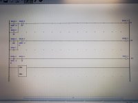
RS Logix 5000 bit toggle

I learned this years ago from a Japanese company that I used to work for. It will work on any PLC. If you need it to stay toggled when power is cycled change the first coil to a latch and add an an unlatch to the last rung. Otherwise it resets itself when power is cycled.

PB ON-OFF-0N PL
-] [ ---]\[----------------( )
PL |
-] [--

PB PL ON-OFF
-]\[----------] [----------------( )
ON-OFF |
-] [-------

ON-OFF PB ON-OFF-ON
-] [--------------] [----------------( )
ON-OFF-ON |
-] [-----------
 
I know this has already been adequately answered, but for future reference and reading relay (ladder) logic, you will not find a better step by step tutorial than the first several videos in @Ron Beaufort's series here: https://www.plctalk.net/qanda/forumdisplay.php?f=2 - key takeaways will ideally be an understanding of the scan cycle and how the PLC evaluates logic, after which all relay ladder logic will be an open book.

Also, almost all relay logic uses one or more of the patterns found here: http://www.contactandcoil.com/patterns-of-ladder-logic-programming/. For example, this toggle (a.k.a. XOR a.k.a. flip-flop) circuit uses what is essentially a cross between the Start/Stop and State Coil/Fault Coil Circuit patterns.

* ... and you never see them on the weekend.

_

I couldn't find the @Ron Beaufort's series in the link that you sent, could you please check again for us, thanks
 
Originally Posted by Doug-P
I've heard of it being done with bit zero of a counter. This also eliminates the need for a one-shot.
That's what I do most of the time.
The counter also ignores any overflow, which can cause a fault-and-halt in some PLCs.

If you don't have a counter with it's built-in one-shot, here is a way to do the same thing without an overflow-prone increment (as long as the_int is not less than -32766):
Code:
  Trigger        Trigger_M       ________________
----] [------+------]/[---------[SUB             ]---+---
             |                  [SourceA        1]   |
             |                  [SourceB  the_int]   |
             |                  [Dest     the_int]   |
             |                   ----------------    |
             |                                       |
             |   Trigger_M                           |
             +------( )------------------------------+
 
I learned this years ago from a Japanese company that I used to work for. It will work on any PLC. If you need it to stay toggled when power is cycled change the first coil to a latch and add an an unlatch to the last rung. Otherwise it resets itself when power is cycled.

PB ON-OFF-0N PL
-] [ ---]\[----------------( )
PL |
-] [--

PB PL ON-OFF
-]\[----------] [----------------( )
ON-OFF |
-] [-------

ON-OFF PB ON-OFF-ON
-] [--------------] [----------------( )
ON-OFF-ON |
-] [-----------

Thats how i do it. Keep it simple. Yes its longhand in a way but i prefer it.
 
Fixed typos, put in [cod_e]-[/cod_e] block.

Code:
 PB     ON-OFF-ON          PL
-] [--+-]/[----------------( )
      |
 PL   |
-] [--+

 PB           PL                 ON-OFF
-]/[-------+--] [----------------( )
           |
 ON-OFF    |
-] [-------+

 ON-OFF           PB                 ON-OFF-ON
-] [-----------+--] [----------------( )
               |
 ON-OFF-ON     |
-] [-----------+
  • PB is the input; a 0-to-1 transition toggles the output (PL).
  • PL is the output.
  • ON-OFF and ON-OFF-ON maintain states internally (scan to scan).
I know it works but I am still trying to grok the approach; I think it may be similar to a counting circuit.


N.B. The way it is written, with the PL output rung first, means the PL does not toggle from 1-to-0 until one scan after the PB rising edge occurs; this could be remedied by moving the PL output rung from first to last in the programmed per-scan sequence.
 
Last edited:
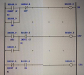
Opps. That is suppose to be R300.0
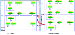
Thanks. Then your logic is more or less the same as @Rockfordmfg's, where


  • PB (@Rockfordmfg) = R0100.0 (@bill4807)
  • PL (@Rockfordmfg) = RO200.0 (@bill4807)
  • ON-OFF (@Rockfordmfg) = RO500.0 (@bill4807)
  • ON-OFF-ON (@Rockfordmfg) = RO300.0 (@bill4807)
I am pretty sure that the difference is that the rungs are re-ordered so that the seal-in for ON-OFF/R0500.0 is not needed.
Untitled.png
 

Similar Topics

Hi, I'm just looking for a simple way to make a button in excel (via VBA I presume) to toggle a bit in RSLogix 5000. I just got FactoyTalkLinx...
Replies
9
Views
551
If any of you wizards can help in this I would be ever more grateful. We have this device that generates 9 second pulses coming into a DI module...
Replies
31
Views
3,622
How can I achieve the same functionality in Studio 5000? Image 001.png for the old RSLogix500 program Image 002.png for conversion to Studio...
Replies
6
Views
2,526
Hello, I'm using Compact Logix L33 in RSLogix 5000. I'm trying to message over modbus register that is 16bit UINT. In Rslogix 5000 do I message...
Replies
3
Views
1,522
Hi there, I am accustomed to working with Logix 500 but have a program modification I need to do on a CompactLogix.... I created a timer...no...
Replies
7
Views
2,456
Back
Top Bottom