Scan counter question

Akbrewer

Member
Join Date
Aug 2020
Location
Juneau, Alaska
Posts
11
Hello!
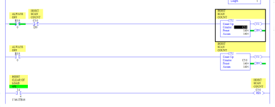
I have a question about a routine I found on one of our box palletizing machines. I've attached the 3 rungs that I have the question about, this is using Rockwell RS500 on a 5/04 processor.

I'm trying to figure out how the C:5 scan counter works, it uses an always off bit being false on one rung and true on the next rung, these two rungs will increment the counter as long as the counter hasn't finished. I'm assuming this is basically using the PLC scan time to run up the counter? I'm still trying to wrap my head around how an "always off" bit is ever actually active, but it seems to work and has been on this machine for years this way.

This C:5 counter is being used as a high speed counter to stop a motor at a specific position. I found today that after I added some additional program instructions to this PLC and another output card to the PLC that the position of the motor stopping point has changed. I'm assuming its because the scan time of the processor changed because it has more actions to compute and control?

Is there a more repeatable way to set up this counter without having to rely on the processor scan times not changing? I thought about trying to use the S: system time to do this process but just wanted to see what anyone else thought about this.

Thanks for any ideas.
scan counter.png
 
On SLC or micro the counters will continue to count if the logic is false to true, the OP has used a second instance of the counter to effectively make it see a false or it would not count second time round, definitely unusual.
As the count will rely on scan time then yes any addition will decrease the number of counts. so for example if the scan time is 100ms then you would get 10 counts per second, however, increasing the logic to be processed will increase the scan time by an amount for example if each extra instruction took 3ms to execute adding 10 instructions will increase the scan time by 3 x 10 i.e. 30ms. (Note: instruction execution times vary depending on the instruction this was just an example).
Given that you made a small change then it appears that the original is on a wing & a prayer, in other words, increasing the scan time has altered the time expected for example if it was used as some king of positioning of a drive then if the scan time was 100ms & the position required was 140 then it would take 140 x 100 = 1400ms or 1.4 seconds, increasing the scan time would put the position further along, normally this would be done with a high speed counter & encoder for accurate positioning.
If it is going further out of position without looking at the complete logic perhaps change the pre-set to a lower value as a quick get around.
I did a project on a palletizer by retrofitting it with a star wheel & proxy to give pulses, this measured the pallet length to position it in particular position in the palletizer to strap in the correct place, this worked so well that they asked me to modify another, however, that one had no space spare on the I/O or spare capacity to fit another card the panel was so cramped so a quick solution was to use a timer of a very short time base i.e. 10ms, great it worked within the tollerances allowed, however, apparently they had a CPU failure & fitted a processor with a higher spec, the scan time was a lot lower & threw the positioning out, again without completely re-building the panel to allow room for extra I/O the only option was to re-calibrate the positioning i.e. change the values for the positions.
EDIT: The examples I posted are just examples instruction execution times will probably be in micro seconds, also is it the counter done bit used to stop it in position or a compare somewhere.
 
Last edited:
PLC5 has STI and PII type setups which are for runners of the use of timed interrupt and event driven programs. These will give you a way to trigger logic that runs periodically or by event. That way a varying scan time will not effect the positioning of the motor.

STI = timed interrupt
PII = event driven interrupt.

Put the rungs that do the motor positioning into a routine and call the routine by either an STI or PII.

Both are setup in the processor status menu.
 
Watch the first two or three of @Ron Beaufort's most excellent PLC bootcamp videos at this link.; it will take about half an hour but it will set you up properly for the rest of your career with PLCs and relay logic. It is also very much worth watching the entire series (2h), but for the purpose of this thread you will know all you need to know after those first few.

TL;DR

ALWAYS_OFF
---]/[------


From Ron's videos, that means "look for a 0 in tag ALWAYS_OFF"

  • I.e. that XIO instruction evaluates the statement "ALWAYS_OFF's value is 0" as either True or False
    • Since the value of ALWAYS_OFF is always 0, that statement always evaluates to True
      • Since that statement is always True, the online display of that instructions will show the green highlights on either side
        • N.B. there are exceptions to that rule about what is displayed, but let's leave it there for now; Ron's videos will provide the knowledge to understand the exceptions and keep it from ever being confusing.
  • A subtlety not to be forgotten is that that instruction also performs a logical AND of the result of that statement with its input rung state (True or False), and it is the result of that logical AND that is place on the output rung of that XIO instruction.
    • In the case of the feed rung to the first instance of the CTU [XIO ALWAYS_OFF XIO HOIST_SCAN_COUNT/DN CTU C5:0 140 ...], that input rung comes from the always-True left rail at the left terminus of the rung,
      • so the input rung to that [XIO ALWAYS_OFF] is True
        • and the instruction evaluates the logical statement
          • True (input rung)
          • AND
          • True (ALWAYS_OFF is 0)
        • which evaluates to a result of True,
          • so it assigns the value of the output rung of [XIC ALWAYS_OFF] to True.
As an exercise, which you can post here or not, run that rung [XIC ALWAYS_OFF XIO ALWAYS_OFF OTE ALWAYS_OFF] in your head using Ron's approach, and do it for two cases:

  • Case 0 with ALWAYS_OFF being 0 when the evaluation of the rung logic starts;
  • Case 1 with ALWAYS_OFF being 1 when the evaluation starts.
To cut to the chase, you will get the result that the value of ALWAYS_OFF will, in both cases i.e. "always," be assigned a value of 0 by the OTE at the end of the rung.


...
 
Last edited:
Bonus question: given the presence of the [XIC ALWAYS_OFF XIO ALWAYS_OFF OTE ALWAYS_OFF] rung, which ensures that the value of ALWAYS_OFF is always 0, would the result of the logic on the rung feeding the first instance of the counter change if the initial [XIO ALWAYS_OFF] instruction were removed?

N.B. this is the same as asking if the state of the input rung to the [XIO HOIST_SCAN_COUNT/DN] would change.

(cue Final Jeopardy music;))
 
Last edited:
The problem is that you are in effect relying on time to tell you when you are in position. The number of scans (140) takes a certain amount of time. Any changes in the code or even in the process can affect the process and throw the timing off. Is it possible to get real feedback to identify when you are in position?

If you must go by time/scans, an alternative could be to use a Selectable Timed Interrupt (STI). This is a special ladder routine that runs on a timed basis. It will interrupt the running code and execute a subroutine one time and then return back to the main code. This logic would not be affected by adding additional code.

And yeah, that second counter logic is a very clumsy way to reset the CU bit to allow the count to execute on the next scan. When I need to do this I put an OTU of the CU bit on the top and then add the CTU in a branch below the CTU.

OG

EDIT: Jim3846 beat me to the punch on the STI. However, they are using an SLC so there is no PII. The equivalent in the SLC is the DII.
 
Last edited:
To address the main question of the original post, the rungs shown are

  1. an overly complex and poorly implemented
  2. "poor-man's timer,"
  3. using the scan cycles as the clock's oscillator.
(3) Scan times are not constant from scan to scan; that said, for a simple program they will have a fairly constant average if enough samples are taken; in this case 140 scans is probably enough to get a consistent average, which means the sum of 140 scan times will be reasonably consistent.

(3.1) As noted by others earlier in this thread,, adding code to the program will increase the scan time of every scan by some amount, so the average scan time will increase, so the sum of 140 scan times will increase.

(2) As noted by others earlier in this thread, whoever did this found out empirically how many scans were required (on average cf. (3) above) to give the correct duration in time from the scan when the (not shown) RESet instruction of counter object C5:0 (HOIST SCAN COUNT) executies and the scan, 140 scans after the RESet executes, when C5:0/DN changes to 1.

(2.1) I am curious why the original programmer did not use a TON (Time delay ON) instruction, which would be able to count some number of milliseconds and assign a 1 to the value of a timer object /DN bit when the required time had elapsed.

(2.1.1) Perhaps the median, or even 70-90th percentile, scan time is shorter than a millisecond, so this approach usually provided a better time resolution than a millisecond counter.

(2.1.2) Or perhaps this program is so old that it predates the availability of TON instructions. Whatever.

(1) Exactly-equivalent logic is far more simply implemented like this (updated to but [GEQ ... OTE] after the ADD):

counted140
----]/[----------[ADD ]-----
[SourceA count]
[SourceB 1]

counted140
---[GEQ ]-------( )-----
[SourceA count]
[SourceB 140]
[Dest count]


### And somewhere else, instead of what I assume is currently [XIC SomeLogic RES C5:0]:

SomeLogic
----] [----------[CLR ]---
[Source counted140]

 
Last edited:
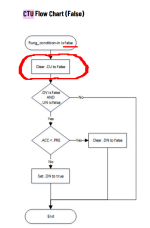
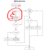
Following up on what was said earlier by others about the .CU bit, here is the flowchart logic for the CTU instruction; it is from Logix 5000 (cf. this link), but that is unlikely to be different from how the SLC has implemented this instruction for time immemorial.

Note especially the logic involving .CU bit, highighted in red; it ensures that counter accumulates the .ACC value by 1 only on a rising edge of the input rung. That is why the original programmer had the two instances of the CTU instruction with the same counter object (C5:0): the second CTU rung, with [XIC ALWAYS_OFF], passes a False input rung to the CTU, which makes the CTU assign 0 to the .CU bit. Then, on the next scan, if the first CTU input rung is True, that CTU will detect that True input rung as a rising edge and increment .ACC.

xxx.png yyy.png
 
I thought about trying to use the S: system time to do this process


Yes, this is best as it ties the bits controlled to an actual clock instead of an average scan time (assuming, as noted by others, that it is not possible to use a physical signal to know when to stop the hoist).

The S:35 (free-running clock) and S:4 (change in free-running clock since the previous scan) have a resolution of 10ms, so unless your average scan time is longer than 10ms, your situation will not improve. Accumulating S:4 values would be the cleanest way to go here, to avoid extra code necessary to deal with S:35-rollover issues when calculating the differences between pairs of S:35 values.

The time base for STIs defaults to 10ms, but that time base can be decreased to 1ms via an [XIC S:1/15 OTE S:2/10] rung, so that would be another way to go that would yield accuracy of ~1ms plus scan time; the link provided by @parky has almost exactly the logic you want to use: add 1 to an INT; I would do as little as possible in the STI routine to ensure the watchdog does not expire*; this assumes the continuous scan time is still short enough to control whatever output needs to change when the desired time (equivalent to 140 average scan times before the recent changes).

* although if all of the logic to control the hoist could fit, in time, within the STI then why not?

The RHC/TDF instruction pair (c.f this link) uses the 20-bit 100kHz free-running clock get down a resolution of 10μs, plus scan time, which should be the best option. Also, the RHC instruction can write directly into Float values (F-file), and assuming the TDF handles the rollover, this should be pretty painless. TDF without rollover is limited to timestamps within ~10.48575s. So if the current 140-scan trigger is calibrated for ~100ms/scan**, then the total time duration of 14s exceeds that, and you would have to run the RHC/TDF pair every scan to get an increment of 10μs counts since the previous scan, which increment you would accumulate the running total in a third float, and then move the latest RHC-retrieved Dest value/TDF Stop value into the TDF Start value to be ready for the next scan; i.e. treat each [TDF Dest] result like S:4 in the paragraph above.

** if the average scans were this long i.e. 100ms, then switching to the S:4 method to get 10ms timing resolution would be good enough and probably the best way to go.
 
What I do for scans computing is have a bit toggle itself every scan, then use that to count up. Run for 1 second then multiply the accumulator by 2. The most it will be off is 1 scan count


XIO BIT OTE BIT //Toggles On/Off every scan
XIC BIT CTU C5:x //Counts up every other scan


As this was used to position a motor counting scans was a bad shortcut to do it.
 

Similar Topics

Will someone please double check my logic I created using the online simulator? The logic was built to tell me scans per second.
Replies
0
Views
1,668
Hi everyone, I'm trying to simulate any program in control expert and see a register in Modscan32 or any software to do that (Like ModbusPoll). I...
Replies
0
Views
102
I am not sure if this is possible but if there is a way, you guys would be the ones to know. I am currently working on a project where we are...
Replies
7
Views
226
I have a Type C to RS485 adapter connect to my Siemens RWF55. I use modscan to scan it to get a value from the Siemens controller. In the...
Replies
4
Views
104
Hi, I'm new to PLCs and learning about PLC Scan times for Schneider PLCs I've derived the PLC scan time using the free running blocks. The PLC...
Replies
7
Views
680
Back
Top Bottom