Servo motion X,Y,Z gantry with a angled Z

Moosetracks

Member
Join Date
Apr 2016
Location
Missouri
Posts
35
I plan to use a profile sensor or something like that measure the distances between the gantry’s Z height and the Z height of the conveyor. Ideally the two would be parallel, but in the real world there will be some variation. So, my plan is to take Z heights all along the conveyor and have a mesh (a 3d representation using points). Then when I need to move to a specific part of the conveyor, I can use the mesh to determine what the conveyors Z is at that point. Are there any built in means to handle this in the PLC, or a common approach to doing something like this that I could use so I am not reinventing the wheel?
 
A lookup table (array) with X, Y as the indexes to get to point Z point (measurement, offset, etc) is the most straight forward. Then, you just got to populate it.
 
I like that idea.

Would you do something so when my gantry is at 3.4,4.5 that it would truncate and round to the resolution of the mesh (3,4)? something like that?
If you want a 10x finer resolution than I would multiply the X and Y by ten, truncate or round, and use the results as the indexes.
 
camming is a form of interpolation, and I think some PLCs have instructions that execute master-follower relationships, those may not be suitable for 2-D interpolation, but perhaps could be adapted for same, if the sample points could be entered on the fly.


Linear interpolation could solve this with three scaling instructions, assuming a rectilinear grid of sampled data.

What brand and model of PLC is in play? Does it have a MODulo instruction?
 
Last edited:
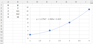
In cases like this I usually use Excel to make a scatter plot of the known points, then add a trendline. Excel will show you the formula it comes up with for the curve, so you can just plug that into a compute function or series of math instructions in your PLC.

EDIT: On rereading the original post I see that a 3D scatter plot would be necessary. Unfortunately I don't believe Excel can do this.

scatter.png
 
Last edited:
I am using an AB control logix for this project. I see a MCCP motion calculate cam profile instruction. It looks like this may work to use that instruction to create the cam profile.

As far as doing it with 3 scaling instructions. I want this to also be able to account for dips or swells along the conveyor as well as not being parallel, but that is a very good idea if it was flat.


camming is a form of interpolation, and I think some PLCs have instructions that execute master-follower relationships, those may not be suitable for 2-D interpolation, but perhaps could be adapted for same, if the sample points could be entered on the fly.


Linear interpolation could solve this with three scaling instructions, assuming a rectilinear grid of sampled data.

What brand and model of PLC is in play? Does it have a MODulo instruction?
 
Thank you. I was thinking about the interpolation formula wondering how to do it. Its so much easier when you know what its called!
Say

  • X is either at Xn or between adjacent sampled points Xn and Xn+1
    • fx = (X - Xn) ÷ (Xn+1 - Xn)
      • so 0 ≤ fx < 1
  • Y is either at Ym between adjacent sampled points Ym and Ym+1
    • fy = (Y - Ym) ÷ (Ym+1 - Ym)
      • so 0 ≤ fy < 1
  • ZXnYm is the elevation at (Xn,Ym)
  • ZXn+1Ym is the elevation at (Xn+1,Ym)
  • ZXnYm+1 is the elevation at (Xn,Yn+1)
  • ZXn+1Ym+1 is the elevation at (Xn+1,Ym+1)
The linear-interpolation estimate of the elevation at (X,Y) is

ZXY = (1-fx)*(1-fy)*ZXnYm + fx*(1-fy)*ZXn+1Ym + (1-fx)*fy*ZXnYm+1 + fx*fy*ZXn+1Ym+1


Last edited:
As far as doing it with 3 scaling instructions. I want this to also be able to account for dips or swells along the conveyor as well as not being parallel, but that is a very good idea if it was flat.


Linear would be good enough if the sampling resolution is fine enough.
 
I see I misunderstood. I thought above you meant I could scale the whole conveyor from one end to the other as a flat profile.

Were you saying I could use the scale function to scale between the individual mesh points if I needed it. Is that what you meant?

Linear would be good enough if the sampling resolution is fine enough.
 
I am using an AB control logix

SCLaoi X Xn Xn+1 ZXnYm ZXn+1Ym ZYm
SCLaoi X Xn Xn+1 ZXnYm+1 ZXn+1Ym+1 ZYm+1
SCLaoi Y Ym Ym+1 ZYm ZYm Z


where [SCLaoi raw rawlo rawhi eulo euho eu] implements

eu = eulo + ((euhi - eulo) * (raw - rawlo) ÷ (rawhi - rawlo)))


You will spend more code figuring out n and m.
 

Similar Topics

I have programmed servos from a handful of variety of manufacturers and series. Each time I used a PLC without motion functions. I have not worked...
Replies
9
Views
728
I’m fairly new to PLC programming. This is our first machine that uses an FX5 PLC rather than an FX3, and therefore GX Works3 instead of GX...
Replies
1
Views
1,252
Hello everyone, So on Monday morning I'm expecting to have a box of random parts dumped in front of me. I'll create another thread with more...
Replies
1
Views
1,976
I'm having trouble trying to get my servo to actually spin. I can't get it to spin even with the jog axis tool. Here is a screenshot showing what...
Replies
12
Views
4,287
I am trying to couple a servo axis to a non-motion signal, and am currently stuck in a Try->Fail loop. :D The axis needs to follow the laser...
Replies
7
Views
2,018
Back
Top Bottom