Siemens LOGO PI regulating

rQx

Lifetime Supporting Member
Join Date
Oct 2010
Location
Trelleborg
Posts
1,051
Hi,

I'm no expert in PID regulating so I need some advise.

I have a VFD controlled deepwaterpump that is maintaining the pressure in a closed pipe system. There is a valve that is opening when water is needed and closes when here is no need for water. This valve open and close relatively slow.

The Siemens LOGO has only P and I functionality.

As it is I have my P set to 0.6 and I set to 0.3s, this is working pretty good.

When filling my pipes when the valves are closed there is a overshoot, SP is 8Bar and it goes to 10Bar before going down again.

During normal operation when the valve is open the SP is maintained pretty good around the SP. +/- 0,2Bar (the sensor is a little bit up and down, it seems to be interference from the pump)

My problem is that I wan't to limit the overshoot to protect the pipes. But I can't increase the P because then the SP will be fluctuating to mush during normal operation.

I can't change the P and I during operation (due to limits in the Siemens LOGO). I have thought of a solution of using two PI regulator blocks and running them in parallell. One that is fast and one that is slow. The fast one would be active all the time unless the SP is within +/- 0,5Bar of the SP. Would this be a somewhat good solution or has anyone any better?
 
Without knowing much about the process, the simplest solution will probably be increasing the term in 30-50% increments (.5, .7, 1., 1.4, 2, etc.) until overshoot is acceptable.

The downside is slower initial response.

TL;DR


Caveat I:
I am being intentionally lazy here and speaking in qualitative terms; the theory is much more involved (and interesting), but unless OP specifically asks for it it is not needed, and anyway @Peter Nachtwey would do a better job explaining it.

Caveat II: the actual issue may be the slow moving valve, which valve's position is falling behind the PI output; a proper solution may need a different approach.

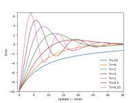
Assuming stable control, IIRC for constant Kp the envelope "containing" the PV will be constant i.e. ± exponential approach to the SP (see image below), and one of the effects of Ti is how quickly the PV rises => the quicker it rises the sooner it gets to the envelope => the sooner it gets to the envelope the higher that point on the envelope.

If the problem is that the slow-moving valve falls behind the CV sent to it, and the process response to the valve is much faster than the valve, then increasing Ti may still help because it will slow down the PI's CV, which could make the CV, and therefore the PV, overshoot less.

Another way to deal with the slow valve might be to read the actual valve position back to the PI's CV value before the PI does each update, although I would be surprised if doing that was even possible in the Siemens LOGO! environment.

Asking The Google to search for terms [PID, critical damping, overdamping, underdamping] will give plenty of examples and theory about this. Slides 14, 15 and 19 of this link show plots similar to mine below, although I think the overdamped case on Slides 14 and 15 are slightly off.

----
The image below shows plots of error (PV - SP) PI control response of a first-order (FO) model* to a step change (of +10) in setpoint.

  • Ti values of 0.25 through 8 are underdamped, but all stay within the ± exponential envelope.
    • Larger Ti values have less overshoot, but respond slower
    • Ti value of 8 is near critically-damped
  • Ti of 16 is overdamped
* N.B. OP's system is probably first-order plus dead time (FOPDT).
Figure_1.png
 
Last edited:
If the valve is "relatively slow" then increase the I-time.
The real question is what is more important; No overshoot or slower pressure rise?
If you dont have access to derivate function you are more or less limited to the above question.


You can always go up to a siemens S7-1200 for moderately higher price but with alot more general functionality and with real PID (with D).
 
This is a difficult situation.
Maintaining pressure in a closed system is extremely difficult.
The pressure can be maintained if the flow in is equal to the flow out. If the flow in is greater than the flow out then the pressure will increase rapidly because water doesn't compress much especially when the pressures are so low.

The valve is probably too slow to do what you want to do. A valve that controls pressure should be fast. Very fast. It should have a zero overlapped spool with very low hysteresis.

I normally deal with hydraulic oil. Water is 50% "stiffer" or non compressible than oil. The bulk modulus of oil is about 200K PSI, For water it is about 300K PSI. Water doesn't compress much. Timing in milliseconds is required which is why the cheap Siemens controller might not ever work well.


You really need a derivative gain if you want to control the pressure accurately.

@drbitboy, nice chart but it is irrelevant. Your time scale is too long.
 
The OP isn't controlling pressure with the valve; the valve is how water gets out the closed system. The control of the pump speed is what is regulating pressure.

I'm not familiar with the LOGOs PI controller. Can you enable and disable it? Upon initial start up of the pump you could simply ramp the VFD up slowly with an incrementing register for the speed reference until you reach say 90% of the pressure SP. Then disable the ramp and enable the PI controller.

This is correct. The valve is on/off but is slow moving. The system is a watering system for crops, the system is diffrent each year (in terms of length) it can be 100m and it can be 1000m. The watering machines can connect anywhere on the line and also up to three machines can be connected each time.

What I currently have is that I run at reduced speed up to 60% of the SP and then go over to PI regulating, but this is just when we fill the pipes so only first time. When there is no water outtake the pressure in the line is maintained and when a watering machine opens up it's valve there is a flow meter that we use to activate the PI regulating.

It's the overshoot that is the problem, not the time it takes to reach the SP. A longer Ti would solve this?

/Tim
 
Just to be clear, you are controlling pump speed to control pressure, not a valve. Is that correct? A couple of earlier posts seemed to be geared toward controlling a valve to control pressure.

It would be nice if you had an accumulator. The heart of the issue is the PI controller is not changing the pump flow rate as fast as the valve is changing the flow rate requirement. When the valve closes you need to get rid of all the integral sum that has built up to satisfy the required flow. This requires error and time. That equates to overshoot. If you had something that could accept water and reduce the rise time of the pressure to allow the integral to reduce you might have a chance.

If you have information about when the valve is closing you may be able to reset the integral sum when the valve is closing and operate on proportional only control. It won't be great but it will keep the pressure down. But this only really works if you have one valve. If you have multiple valves it is a little more complicated.

Keith
 
Aside from generally improving the tuning parameters, here are two other ideas:

1. Make the valve close slower
2. When you know the valve is closing, limit or manually lower the pump speed immediately.
 
It's the overshoot that is the problem, not the time it takes to reach the SP. A longer Ti would solve this?


So the overshoot is to a higher pressure than setpoint, so I assume that means it is when the valve is closing. Is that correct?


And the valve closes all the way i.e. to zero flow out of the syste? In that case, I don't think a longer Ti would help; ask @kamenges says you need to a way to either get rid of the integral bias quickly, or make the system respond more slowly via an accumulator. Is this analogous to a slow-motion water hammer?


Can you provide a trend of the behavior, along with a many relevant variables as possible: PV; actual actual valve position; CV (speed reference); actual motor speed; flow rate; etc.?
 
Just to be clear, you are controlling pump speed to control pressure, not a valve. Is that correct? A couple of earlier posts seemed to be geared toward controlling a valve to control pressure.

------------
If you have information about when the valve is closing you may be able to reset the integral sum when the valve is closing and operate on proportional only control. It won't be great but it will keep the pressure down. But this only really works if you have one valve. If you have multiple valves it is a little more complicated.

Keith
Yes, I'm controlling the pump not the valve.

I have no information if the valve is closing other then the pressure building up. If I reset the Integral (deactivate and activate the PI-block in LOGO) when the pressure goes over my SP (with some margin) maybe would be an alternative?


Aside from generally improving the tuning parameters, here are two other ideas:

1. Make the valve close slower
2. When you know the valve is closing, limit or manually lower the pump speed immediately.

I think the valve is at its slowest
I have no connection to the valve unfortunally

So the overshoot is to a higher pressure than setpoint, so I assume that means it is when the valve is closing. Is that correct?

When the valve is closing and when filling the pipes from empty

And the valve closes all the way i.e. to zero flow out of the syste? In that case, I don't think a longer Ti would help; ask @kamenges says you need to a way to either get rid of the integral bias quickly, or make the system respond more slowly via an accumulator. Is this analogous to a slow-motion water hammer?
Yes completely closed. Get rid of the Integral, would that be reset the PI-block for example?

Can you provide a trend of the behavior, along with a many relevant variables as possible: PV; actual actual valve position; CV (speed reference); actual motor speed; flow rate; etc.?
I will try to get it but there is no information regarding the valve and flow rate
 
With the PI controller setting the VFD speed reference, only decreasing the Ti value will make it respond quicker when the valve is closed, but then there will me more overshoot during times when the valve is open. It might be better to cobble together and asymmetrical controller, that raises speed slowly when pressure is below setpoint, and drops it quickly, perhaps even more than linearly, when pressure is above setpoint. But LOGO! is ill-suited for that kind of application.


Is there a recirculation from outlet side of the pump back to the pump suction, or perhaps to a reservoir, or even onto the ground? And if there is a recirc, can you control it?

When the valve closes, does the pump speed eventually drop to zero or near zero speed?

I think the system needs either a recirc on overpressure or a pressure relief valve; PI control, or even just P control, is not going to be able to do much with the overshoot when the valve closes.
 
There appears to be a R (Reset?) input to the PI, which when 1 will set the output to 0. You might try triggering that when the PV exceeds the SP by more than some delta, but then you've basically converted to bang-bang control, because when that R becomes 0 again, the controller output Aq reverts to its last value (or maybe a value based on the PV-SP while R was 1).
 
It may be possible to add, external to the PI block, some Derivative action to the controller output.

In normal operation when the valve is open, the pressure would be changing more slowly, so it would not have much of an effect there. Unfiltered D-action would also almost certainly increase (chase) the noise in normal operation, but to counter or eliminate that effect it could implemented with a deadband, or even a cutoff so D-action only kicks in when the PV is both/either rising and/or at some nominal but significant offset above the SP. Another possibility would be an asymmetric (edge) filter, that passes increases in calculated D-action but attenuates decreases.

Caveats

  • It might not help much
  • It would be clumsy because it's LOGO!
  • Without a deadband, it would add noise to the normal operation
 
Last edited:
You guys are right. A PI controller will not work well. It would be best if the valve position is known. Then it could be used as a bias or feed forward.

My solution is to use a I-P controller. The I-P controller has a normal integrator but the proportional gain is multiplied by the change in the pressure or process variable.
CO(n)=CO(n-1)+Ki*T*(SP(n)-PV(n)-Kp*(PV(n)-PV(n-1)
Notice the -Kp. That is why it is an I-P controller. T is the update period.
To be safe, the whole term needs to be limited by min and max functions
CO(n)=min(max(CO(n-1)+Ki*T*(SP(n)-PV(n)-Kp*(PV(n)-PV(n-1),100),0)
So why does this work? A PI controller adds a zero to the closed loop transfer function and zeros can cause overshoot in a system that won't otherwise over shoot.

One more VERY IMPORTANT thing. Someone above correctly said that an accumulator will help. It will help a lot. An accumulator in a hydraulic systems acts like a capacitor in an electrical system. It will smooth out transients and give the pump and I-P controller time to respond. The bigger the accumulator the slower the pressure will change. If I had more information I could size it. I do this for hydraulic ( oil ) systems.
 

Similar Topics

Hi all, First, thank you for reading the thread. So I had a task as the following: An up-counter must be programmed as part of a batch-counting...
Replies
7
Views
287
Hi Lads, I want to implement a flood prevention system with my domestic water pump. The intention is to have the water pump cut off on a daily...
Replies
7
Views
1,077
We need a Really Simple and Cheap controller that has a display or a Web Interface where we can change some set points. We were thinking about a...
Replies
2
Views
1,045
hello i have LOGO! 12/24RCE and i am looking for a schematics of electronic board. Or if someone know what is the burned component on the photo.
Replies
4
Views
1,409
Hi there, I have three pumps, I have to start first pump for 8 minute and after that it should be turned off and other one start simultaneously...
Replies
11
Views
1,853
Back
Top Bottom