Smoothing analog

I use Mickeys method a lot. I have found that I need to condition the frequency of the filtering to slow it down a bit. I often precede the filter math with a bit from the free running clock and a oneshot.

On a side note, the free running clock is much faster in a Micrologix 1400 than it is in a SLC 5/03. I might use the bit S:4/4 or 5 in a SLC to update the filter every 320 or 640ms, but in the Micrologix I end up using bit 10 or 11. I could just set the filter number to a ridiculously small value and let it run as fast as it can, but I prefer the filter logic to be consistent regardless of scan time by triggering it with a timer or timebase I can control.

May I see a little bit of that codes you are talking about.
 
May I see a little bit of that codes you are talking about.

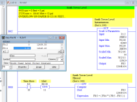
Sure (from a Micrologix 1400).

The rung comment was my note of the numbers I recorded after first powering up the system after being off for two days. The low end seemed to drift around a lot as things "warmed up". The old transmitter had been tampered with and had some notes scribbled on it that made little sense so I basically scaled the level to a mechanical gauge that was trusted by the operator. Even after a few hours, the value was "noisy" so I left the filter logic in place as shown.

Filter_ML1400.png
 
Last edited:
Normally a low pass filter is done like this
y(n)=A*y(n-1)+B*x(n)
where
y = output
x = input
A=exp(-scantime/timeconstant)
B=1-A
If the scan time is 0.01 seconds and the time constant is 1 second then
A=exp(-0.01/1)=0.99005
The filter frequency in radians per second is 1/timeconstant. Divide radians per second by 2PI to get Hz.
This is good to know if trying to filter out 50 or 60 Hz noise.
 
I use the form Peter showed, mostly because you CAN calculate a meaningful value for A based on a time constant if you want to, as Peter showed.

I should modify that statement. You can calculate a value for the filter constant in any form of a digital difference filter based on a time constant. It just isn't quite a direct as when the equation is in the form Peter shows.
Keith
 
Last edited:
Normally a low pass filter is done like this
y(n)=A*y(n-1)+B*x(n)
where
y = output
x = input
A=exp(-scantime/timeconstant)
B=1-A
If the scan time is 0.01 seconds and the time constant is 1 second then
A=exp(-0.01/1)=0.99005
The filter frequency in radians per second is 1/timeconstant. Divide radians per second by 2PI to get Hz.
This is good to know if trying to filter out 50 or 60 Hz noise.

Thanks Peter. The refresher course is much appreciated.
 
y(n)=A*y(n-1)+B*x(n)
where
y = output
x = input
A=exp(-scantime/timeconstant)
B=1-A

FV=FV+C(NV-FV)
Where:
FV= Filtered value
C= constant (range 0-.99) The smaller the number the more dampening.
NV= New Value

Filtered Value= Filtered Value+Constant*(New Value-Filtered Value)

Please realize that these two methods are mathematically identical.
But if you're implementing them the one Mickey posted is maybe a little faster since there is only one multiplication operation needed.

A lot of PLC have input filtering on the analog input as well. Some of them with bandpass filters selectable to 60/50 Hz. Some of this is done in software.

But it's also important to investigate why the signal needs filtering. Is the analog input wiring shielded? Is it 4-20mA instead of 0-10V. Is it run correctly (not close to power lines/VFDs etc). And of course what are we measuring and where is the sensor located? Sometimes we are trying to solve a hardware problem with software instead of doing it right.


.
 
Last edited:
But it's also important to investigate why the signal needs filtering.
I'll second that. It is better to keep the noise from getting to the PLC or motion controller than filter it later.

There is another thread about bragging our projects. In the FAA project they originally had 3 Hz filters on their analog signals. Without the 3 Hz filter the analog signals were unusable. They showed me graphs of how the system was controlling before but what they were controlling was the filtered positions and forces. They couldn't see the force spikes as the tires when up and down over the ruts. They really didn't know what was really happening. After getting the system to work somewhat I went home while the engineer re-wired the machine to remove the noise and the 3Hz filters. The data didn't look any better with the new system but it was real.
 

Similar Topics

Hello, I'm pretty new to RSLogix 500. I'm trying to smooth out the raw analog input. Current 4-20ma. I'm in an environment that I can not control...
Replies
5
Views
2,993
Hello, I am using a P1000 CPU (P1-540) with a P1-04DAL-2 and a P1-04ADL-2 I tried doing a data transfer now I am trying to scale them both...
Replies
0
Views
1,111
Mickey has posted a formula for doing this that a lot of people seem to make use of. Could somebody please give a simple "Ladder" diagram as to...
Replies
22
Views
12,276
I am trying to make an input less jumpy. The monitored input has large spikes, and changes too fast. I am trying to smooth it out. I am using...
Replies
2
Views
2,143
Good morning guys, So i know this is extremely basic, but im just starting our with analog signals and trying to wrap my head around it. I...
Replies
10
Views
4,347
Back
Top Bottom