"Sts_Overload" Modbus TCP and Studio 5000 AOI Client/Server

mnwinter

Member
Join Date
May 2020
Location
Seattle
Posts
12
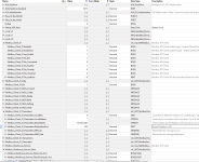
So I am working on a project and I am having problems trying to get this all to work. I had it working but lately I have been getting a fault on one of my Modbus TP Client AOIs. I have the Sts_EN enabled but the AOI keeps swapping bewteen "STS_faulted" and "Sts_Overload". But I cannot find anything online or in the help manual about it that came with the AOI. Can anyone help me figure out what is going on and why this is happening. Thanks.

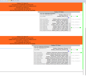
Screenshot 2022-10-24 073302.png Screenshot 2022-10-24 073416.png
 
That AOI will signal overlap and overload if it is not getting expected responses from the server, especially if the server completely ignores a client transaction. I ended up abandoning the AOI, but used some of it as an example to write a simplified client. Its code is not particularly readable.
 
Your screenshot shows error -9 that is "Connect" message error.
Looks like -9 code is missing from the manual, but tag descriptor has it.

My guess is that device address may be wrong?
Or local slot number?
Hard to say without any details.
 
I gave up trying to use that AOI also. No matter what i used for message timing and periodic task timing, I continually got overloads, overlaps, and even worse minor plc faults.
 
lol. I eventually rolled my own because of the initial version’s issues.

For your case, make sure that the AOI call is happening in a task of at least 10ms period.

Your second screenshot indicates that you need to assign a local address (PLC interface IP). You have only set the destination (gateway/endpoint). The Socket object requires both to function.

Sts_Connected relates to the IP side of the exchange.
 
Last edited:
^ He's right. There was a version 2.04 released on October 22, that says addresses some overload and minor fault issues. Try upgrading you add-on to this new version. I'm going to give it a try as well.
 
Regarding version 2.04:
I am told that the minor faults we traced to devices that combine multiple Modbus responses into a single TCP packet.
As a result, 462 byte strings were not able to handle incoming data with size up to 484 bytes, generating minor faults.
The new version 2.04 increased buffer up to 500 bytes.
I did some tests with Micro 850 as a server and I clearly saw combined Modbus packets with multiple large size transactions.
In my case Minor Faults in L7x controllers are no longer present.

Also from my experience, if you have "Sts_Connected", Overloads and no data, then in most of cases it would be incorrect StationID specified in each transaction.
Default value is 0, but some devices use other numbers, mostly 1.
Check device manual for the exact number.
 
lol. I eventually rolled my own because of the initial version’s issues.

For your case, make sure that the AOI call is happening in a task of at least 10ms period.

Your second screenshot indicates that you need to assign a local address (PLC interface IP). You have only set the destination (gateway/endpoint). The Socket object requires both to function.

Sts_Connected relates to the IP side of the exchange.

You were right I had clicked on the wrong box, I updated the local address correctly. Then limited the total registers needed to the first 40 not the first hundred. This seemed to reduce the faults and overloads to almost zero.

I am however curious I have never written my own Modbus Communications, is there a resource that I could read to understand how to do this. I am a patch PLC programmer I have done very basic programs, outside of that its all modifying others/old code. Thank for all the help from everyone though!
 
Assuming all else working, you may have run into one of the odd idiosyncrasies in the Modbus protocol which is the concept of a “write-only” register. If one of these is among the group you are trying to read, the transaction will fail. It’s dumb for a device designer to have placed a write-only register among those accessible, and it’s even dumber for the protocol to support it in the first place.

You could theoretically read many more than 40 at a time. Endpoint devices have their limitations.

If you go to write your own comms libraries, you first need to have a grasp of the protocol.

The Modbus spec is easy to obtain.

Rockwell’s and my own Modbus TCP clients are just specialized drivers for the Logix Socket object and its services. Sockets are generic TCP/IP interfaces. Both clients just handle boilerplate TCP/IP socket work and then get into the Modbus TCP payload handling.

You can use the Socket object to do comms in other protocols that establish connections this way.
 
Last edited:
I have never written my own Modbus Communications, is there a resource that I could read to understand how to do this.

Start simple and work your way up.

Look up client-server architecture, and find a "hello world" example in an easy scripting language like Python or Javascript, or even C.

Make sure you understand what is going on both in the client (connect) and in the server (bind/accept).

The WSL (Windows System for Linux) was an add-on to Windows 10 that allows easy experimentation with command-line apps.

Then read the technical documentation about Modbus at modbus.org. The documents are quite readable; don't get swamped with the details, just remember that 90% of most applications is bookkeeping i.e. keeping track of the bits, whether those are discrete bits or bits grouped as INTs or DINTs or REALs. The Modbus protocol is almost completely based on 16-bit MSByte-first unsigned integers. Pay particular attention to the byte order of multi-byte entities (addresses, lengths, etc.).

Then write a Modbus TCP Client/Server pair in something like Python; that's a fairly small step from the hello world example once you understand the protocol (see previous protocol).

As with anything, break it into bite-size tasks:

  • build a message into a stream of byte data, be those data "hello" or a Modbus request.
  • write a TCP server that binds an [IP,port] pair (IP will be localhost or 0.0.0.0) and accepts connections
  • write a TCP client that connects to an [IP,port], and prove it works by having the server above print "accepted connection" to the terminal in response
  • modify the TCP server to read the accepted connection
  • modify the TCP client to write data to the connection, and prove it works by having the server above print "received data" to the terminal.
  • modify the TCP server to, after receiving the client data, to send response data (e.g. the current time plus "OK," back to the client over the connection
  • modify the TCP client to read the response from the server, and prove it works by having the client print "received response YYYY-mm-ddTHH:MM:SSOK."
  • By this point, you have more or less duplicated the hello world examples.
  • modify the TCP client to create a Modbus protocol message (ADU = additional (modbus unit, usually 1 or 0) address (1 byte) + PDU (1 to 253 bytes); Modbus TCP needs no CRC; PDU = function code (1 byte) _[1 to 252 bytes)) as data, and print it to standard output, but converted to hexadecimal so you can read it.
  • modify the TCP server to parse a Modbus protocol message; don't worry about fully parsing the PDU beyond the function code yet.
  • modify the TCP client to send that Modbus protocol message to the server connection, and prove it works by having the server print the additional address and the function code (first byte) of the PDU.
  • modify the TCP server to parse the PDU for one type of function code e.g. 3 (0x03) Read Holding Registers, so it will see the byte 3, parse the next two bytes as an MSByte-first offset into the server's "holding registers," and the next two bytes as an MSByte-first quantity of registers requested.
  • modify the TCP client to generate a Read Holding Registers Modbus protocol request and send same to the TCP server, and prove it works by having the server print out the details of the request (additional address, function code, offset to starting address, request quantity).
  • modify the TCP server the generate data for a response by taking the addresses requested (e.g. modbus address offset = 16 and quantity = 3 => 16, 17, 18), subtracting each from 65535 (so 65519, 65518, 65517) and converting those to a Modbus response (additional address, function code, 2-byte byte count, register data), and sending that message (add'l address, 0x03, 6, 65519, 65518, 65517) as a response to the client
  • modify the TCP client to read back those data, and prove it works by parsing those data and printing the results to standard output.
Each one of those steps is typically, and often far, less than a couple dozen lines of code. Extra points if you break each step into its own method, to make it easy for the main program to choose between methods later (e.g. call parse_read_holding(method) if function code is 3; call parse_read_discrete_inputs(method) if function code is 2; call retrieve_holding_registers(method) if the parse_read_holding(method) found a valid address offset and quantity; etc.).

What's next is up to you: convert that from Python (or whatever) to a PLC socket interface; add other function codes; etc. Also: good writers borrow; great writers steal; but make sure you understand what you are stealing.

It's all bookkeeping. As Jouni Ryno wrote: "It's just zeros and ones, it cannot be hard"
 
I think an excellent pet project could be to create an EtherNet/IP adapter/scanner that used the Socket object to establish and maintain extra connections beyond the node count allotted.
 
Check your TCPOpen() instruction if your Modbus TCP socket connection has failed. The socket that TCPOpen() returns ought to be less than 99.
 

Similar Topics

Hey all, I have been trying to update the transfer lists on a pair of redundant CPE330s that are currently out running in the field. According...
Replies
1
Views
767
Hey all, I have a quick question about RX3i transfer lists. I was wondering if anyone knows the difference between the input and output transfer...
Replies
3
Views
2,108
Siemens S7/TIA v16: "Overwrite if object exists online?" HMI loading message... Thus far, I've just been ticking this box, just to get the HMI...
Replies
4
Views
774
I am working on trying to send and receive lists of BadgeIDs and User Access levels from a windows application to my system. My current theory is...
Replies
0
Views
621
Not sure if it's a setting somewhere I can change or if it's normal/expected behavior, but if I'm away from this forum for over a day or so (like...
Replies
1
Views
600
Back
Top Bottom