Synchronizing access to PLC data block (Siemens S7 1200)

zoomable

Member
Join Date
Oct 2021
Location
Ontario
Posts
36
Hello all,

PLC-programming noob here.

I have multiple clients accessing some data on my Siemens S7 1211C PLC; some OPC clients and some direct (IE).

To avoid potential race conditions I want to synchronize their access using a lock. How does one do that on a PLC?

The OPC server I am using is the integrated OPC server on the S7-1200.

EDIT: looking at https://www.reddit.com/r/PLC/comments/jj3ab6/siemens_s7_with_wincc_oa_hmi_newbie_question/ , I see that the PLC code really only needs to buffer the inputs from the HMI at scan start time, and use only those values. I think this can work, right?

Much thanks.
z
 
Last edited:
This is a mutual exclusion problem. Operating systems have system calls to gain access to shared resources. PLCs don't have this ability.


The only thing I can think of is have a memory location that keeps track of what device has access to a memory block. Call this location mx. mx should be initialized to 0. To gain access to the memory block the device wanting to access the block should check to see if it is 0. If not then the block is in use. If it is zero the device should write a code into the mx variable and then read back mx to make sure mx has the code that was written. Then the device can access the data block. mx should be reset to 0 when done accessing the data block so that other devices can access the data block.


Now here is the problem. What if device A and device B both want to access the data block at at the same time. Device A set mx ( short fir mutual exclusion ) to its code and device B does the same because it hasn't seen the change made by device B. Device B will over write device A's code without knowing it so device B will be the one with access until it resets mx to 0. When device A reads mx to see if the code belongs to device A it will see that some other device has gain access so device A must wait for mx to be reset to 0 again.
 
Peter explained it well, as usual:

  • there is a target area (memory, tag, etc.),
    • Access to the target area needs to managed in some way so that only one client at a time accesses the target area
  • To manage access, there is a common "lock" area (of memory),
    • in parallel with the actual target data,
    • that all clients can attempt to "claim" (write to),
    • but only one client can "own" the lock area at any time,
    • plus some logic on the PLC to resolve simultaneous claims;
      • that resolution could be
        • arbitrarily accepting one claim among multiple simultaneous claims,
        • or it could be rejecting all claims (like CSMA/CD for Ethernet), and notifying all claimants to try again
      • The actual algorithm is not important, as long as it ensures that only one claimant at a time can "think" it actually "owns" the lock before accessing the target area.
This problem is not unique; tt might be useful to consider how it is handled at the CPU level, e.g. see slides 12 and onward at this link.

N.B. the "lock" is not an actual or physical lock in the common sense of the word: the lock does not actually prevent multiple clients from accessing the target data simultaneously; it is instead only part of an agreement, or contract, between all of the clients (claimants) that each claimant will only access the target data when the locking logic declaresthat claimant obtained the lock.

Another piece of this is how to release the lock, and the edge cases are important. For example, normally a client will obtain the lock, access the target data, and then release the lock. The exact details of how a client releases a lock are TBD, however, what if a client obtains the lock, but then crashes or otherwise loses connection with the OPC server before completing the process and releasing the lock? How and when does the locking logic decide when to release such an orphaned lock?
 
N.B. the "lock" is not an actual or physical lock in the common sense of the word: the lock does not actually prevent multiple clients from accessing the target data simultaneously;
Yes it does. A mutual exclusion doesn't.
The difference is that a lock keeps another master from accessing memory using hardware whereas a mutual exclusion is just a software way of keeping two tasks from accessing a resource. A lock keeps multiple hard ware devices from accessing something at the same time. A mutual exclusion keeps multiple tasks or threads from accessing a resource at the same time. There is a distinction.


The 80186 has a LOCK prefix that can be added to an instruction to keep another device from accessing the bus. This would avoid the problem where device B and device A both want to access the MX location and device B checks MX and sees it is 0 but before device B can write to mx, device A has already written to mx.


One a 80186 the LOCK prefix was often used with the XCHG instruction where the a value can be exchange with MX without the fear of another hardware device accessing MX between the read and write.


it is instead only part of an agreement, or contract, between all of the clients (claimants) that each claimant will only access the target data when the locking logic declaresthat claimant obtained the lock.
That is a mutual exclusion.


Another piece of this is how to release the lock
This is not a problem for the hardware LOCK since it lasts only for one instruction. This is a problem when a task that has the MX set dies.


These are two separate issues. The problem is that the OP has different external devices, not tasks that are trying to access the data block.


I program 80x86s for 30 years. I wrote small real time kernels and some cases there were multiple CPU accessing memory.
 
HI see that the PLC code really only needs to buffer the inputs from the HMI at scan start time, and use only those values. I think this can work, right?

That's not valid for a S7-1200.
In a S7-300 all communication happens between the end and the beginning of a new OB1 cycle. The S7-300 had an option for faster HMI access in the HW-config, where the communication can happen anytime in the OB1 cycle. That's also the default behaviour in S7-400 and always in every S7-1200 and S7-1500.

The S7-400 had a UBLKMOV command, where you are able to copy data which cannot be interrupted from any kind of communication.
The S7-1200 has no possibility for synchronization. The S7-1500 has a highest level of interrupt OB which also cannot be interrupted by communication. The S7-1200 hasn't this.

I've made tests with the S7-1200, where I've found out that you even cannot read consistent string values from an HMI. I've written a string in the PLC with 254 'A' and next with 254 'B', and in some cases the HMI reads part 'A' and part 'B' (AAAAABBBBB). When you have to be 100% sure that this never happens, you need to implement other communications.
 
Yes it does. A mutual exclusion doesn't.


Peter is right of course, there is a difference between a lock and a mutual exclusion. That said, some operating systems have used the term "lock" when they meant "mutual exclusion," which is why I was sloppy with the semantics (Peter is not the only one who has delved into kernel-level code ;)), so if you replace "lock" in my post with "mutual exclusion," it will be in line with what I should have said and make more sense.

The point is that, for the current thread, the OP will have access to neither (device) lock nor mutual exclusion, and will have code the functionality of the latter from scratch, because PLCs are not "thread-safe." Another issue, as Peter mentions, is that the mutual exclusion has to protect against multiple access by not internal PLC tasks alone, but also by external processes using OPC or other communications.

I wonder if a double-buffer would work: the 254-As and 254-Bs are written into two identical buffers, with a separate bit for each, which bits are set to indicate which is the last buffer to be complete, and the readers use the bits to choose which buffer to use and/or display. E.g. an HMI could display the content both buffers, but make only the one with the set bit visible (e.g. make foreground and background colors the same). I dunno, we really don't know enough about the actual application and the clients accessing the data.
 
How about a triple buffer?


  • Buffer 0 contains the source data; these are the original data from whatever writes to them
    • We do not care if these data are inconsistent an any given time, as long as they settle down at some point.
  • Buffer 1 is for staging the data to buffer 2 (below). Buffer 0 contents are copied to Buffer 1 whenever Buffer 1 differs from Buffer 0.
    • These data may also be inconsistent with what is in Buffer 0, if Buffer 0 it written to by another thread while the copy from 0 to 1 is in progress.
  • Buffer 2 is the final buffer, Buffer 1 is is copied to Buffer 2 on the following conditions:
    • Buffer 0 was copied to Buffer 1, i.e. Buffers0 and 1 differed, during a previous scan,
      • I.e. Buffer 0 and Buffer 1 have "settled down."
    • Buffer 0 and Buffer 1 are identical on the current scan.
I think this only kicks the can down the road, as the external processes could be reading Buffer 2 while it was being written, so there would need to be some way to ensure the copy from Buffer 1 to Buffer 2, once triggered, could not be interrupted, perhaps using the DIS_/EN_AIRT instructions, but then why not push that back to wrap those instructions around the original copy of the data into Buffer 0 in the first place?
 
Last edited:
I think this only kicks the can down the road,
Yes, software alone cannot solve this problem adequately.
When 3 devices are trying to access the same resource, that is a mess. I know how Rockwell did it with the SLC500 series with the comm module and the QS controller we made for Rockwell, I also know how Modicon did it on the Quantum series. These applications were relatively simple as there was the master PLC and the slave card and both solutions required special hardware.
Rockwell had the specially designed SPIGOA or "potato" chip. Modicon used an off the shelf dual port memory with two banks that would switch back and forth. Rockwell's solution worked great but I bet it cost a bundle making a special chip for their PLCs whereas Modicon used an off the shelf chip that wasn't a clean but worked just as well and was a lot cheaper solution. My company made the 1746 QS for Rockwell and the MMC120 for Modicon. Both modules were similar in that they used similar code and had similar features.
 
Peter, drbitboy, can you please further elaborate for me? If only one of the clients of the hmi write data to the plc and all others only read; or if multiple hmi clients do write but to different memory areas of the plc, does such configuration need all these considerations?
 
Peter, drbitboy, can you please further elaborate for me? If only one of the clients of the hmi write data to the plc and all others only read; or if multiple hmi clients do write but to different memory areas of the plc, does such configuration need all these considerations?
Even if only one device can write to the PLC, you must be sure that it can be done so that only that device has access to the data block. A problem occurs when device A writes to the PLC while device B is reading. Device A may be writing 1s to the data block that already has 0s in it. Device B may read part of the data block as 1s and part as 0s which isn't what device A is trying to write.


Only one device should access the data block at a time. Siemens calls this a consistent read or write. Other call it an atomic read or write.


This is extremely important when writing to motion controllers because a command that has data from two different sources will not work out well and could possibly be dangerous.
 
Peter, drbitboy, can you please further elaborate for me? If only one of the clients of the hmi write data to the plc and all others only read; or if multiple hmi clients do write but to different memory areas of the plc, does such configuration need all these considerations?

Possibly. Everything that is read must also be written at some point, and all writing is not necessarily by an external HMI or other device.

Consider that the read operations could be happening in a different OB, at a lower priority, than the write operation. In that case, the lower priority read, say an MB_SERVER instruction, could be be halfway through reading some data when it is interrupted by a higher priority write operation (e.g. Profi-something). So the lower-priority read operation stops while the data are overwritten by the higher-prioriy write operation, which changes many of the bits in the data. After the write operation completes, control is returned to the read operations, which picks up where it left off by reading the last half of the data, but that second half of the data that are read after the write are now inconsistent with the first half of the data that were read before the write.

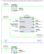
See the image below. This is based on two PLCs:

  • an S7-1200 PLC
    • running a Modbus TCP Server via the MB_SERVER instruction in Program Cycle Organization Block OB1 at Priority 1 (low priority) i.e. the continuous process
      • The Holding Registers (VarIn MB_HOLD_REG) are a 100-character (100 8-bit byte) string, equivalent to 50 16-bit holding registers
    • running a high-priority Cyclic Interrupt Organization Block OB37 at Priority 24 (high priority) running every 5ms,
      • That alternates writing 100 'A' characters (byte value 65) and 100 'B' characters (byte value 66) to the 100-character string at a high-priority, which string is used as the Holding Registers of the low-priority Modbus Server
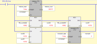
  • a Micro820 running
    • a Modbus TCP Client (MSG_MODBUS2) instruction retrieving 50 Holding Register values from the S7-1200's Modbus TCP Server (above)
    • a comparison of the second and last word of those 50 holding registers that have been read every time the MSG_MODBUS2 instruction completes,
      • which adds 1 to the Tag mismatch every time those two registers differ (see lower right instruction in image)
  • So if the MB_SERVER instruction in the low-priority Program Cycle OB1 always transferred the complete 100-character string (50 Holding Registers) without being interrupted by the write to those same data in high-priority Cyclic Interrupt OB37, then mismatch would remain 0, because the second and last register would either both be 'AA' or both be 'BB' in which case there would never be a mismatch.
    • Since mismatch is not 0, that implies the low-priority MB_SERVER instruction transfers the second Holding Register before an interruption by the high-priority write, and the last Holding Register after an interruption by the write. Only about one Modbus transaction in 1000 is affected, but the important thing to note is that it is not 0.
    • The second image below shows the MB_SERVER enclosed in a DIS_AIRT/EN_AIRT instruction pair, which seems to stop the high-priority Cyclic Interrupt write from interrupting (zero mismatches in over 45k client reads so far).
50words_no_airt.png

50words_airt_wrapped.png
 
Last edited:
@zoomable
Please describe the functionality and the perceived problem a bit more.
There is no functionality in S7-1200 to dynamically block an OPC server to write to an address, when the PLC has made the address accessible via OPC UA.
Also, the writing of data into the PLC address happens asyncronously to the PLC code scan.
To put it short, if several OPC servers writes to the same address, then there is the potential to mess things up.

Is the problem that the OPC servers sends 'tasks' to the PLC, which the PLC must perform, and your concern is what happens when two OPC servers sends a task to the PLC at the same time ?
If so, I think the solution is to reserve separate memory area in the PLC, one from each OPC server. The PLC then handle the tasks after first come first served.
The tasks shall be stored in a FIFO buffer (or 'queue') of tasks, so that the PLC can keep track of the tasks.
 
I dunno, we really don't know enough about the actual application and the clients accessing the data.

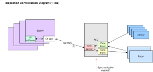
Exactly, I need to learn to add more detail to my posts. Here is a block diagram (why can't I edit my original post anymore?):
view


So, the PLC is single-threaded with interrupts, right? Is it possible to read in all data values at scan start, and use those for the remainder of the scan? Any new values written during an interrupt in the scan could be ignored until next scan, no?

Untitled Diagram-Copy of Block Diagram.png
 
Last edited:
Update: below see an image of the the Micro820 mismatch result with the DIS_AIRT/EN_AIRT enabled on the Siemens side. Cut to the chase: zero mismatches in over a third of a million Modbus transactions with a functional equivalent to a lock in place, whereas there was roughly one mismatch per thousand transactions without the DIS_AIRT/EN_AIRT enabled.

I may put the code up on Github eventually, in case anyone else wants to play with this and/or verify and/or validate my result.

50words_with_airt.png
 

Similar Topics

Hello, I am looking for your suggestions for methodologies to sync process setpoints across a local HMI and remote SCADA system. Background...
Replies
18
Views
2,060
I'd like to hear how others have handled this kind of situation. I have four identical machines, each with a Red Lion CR3000 15" HMI and Beckhoff...
Replies
5
Views
2,505
TLDR; How to synchronize setpoint values between a local HMI and remote PLC connected by cellular modem, while preserving the most recently...
Replies
8
Views
4,101
I'm working on a design for a cutting machine. This system gets synchronized with the production line speed, Do the cutting and come back to the...
Replies
4
Views
2,549
Let's that I want to synchronize 2 digital outputs so the fist DO is ON for 600 ms and a soon it goes to OFF state the second will turn ON for 400...
Replies
1
Views
1,320
Back
Top Bottom