Synchronizing access to PLC data block (Siemens S7 1200)

So, the PLC is single-threaded with interrupts, right?

Whether it's "single-threaded" depends on your definition of "thread." I would assume there is only one CPU (ignoring High-Speed Counters for now), so let's assume that one single-core CPU is only ever doing one thing at a time, and if that is how we define "thread" then there is only one "thread."

However, with interrupts comes the possibility of multiple tasks, or OBs (Organizational Blocks in Siemens jargon), that may stop (interrupt) a first OB to execute a second OB before returning to the first OB, which first OB may not even know the second OB has run. If we define those OBs as "threads," then the PLC is not single-threaded.

(1) Is it possible to read in all data values at scan start, and use those for the remainder of the scan?
(2) Any new values written during an interrupt in the scan could be ignored until next scan, no?

(1) Yes; that is called the Input Map pattern; cf. this link; the Input Map pattern is related to double-buffering.
(2) Yes, but with a caveat: the trick is to prevent any new values from being written (via interrupt by another task*) during activity "(1)" i.e. while the Input Map is executing that initial read at the start of a scan.

* in this case the OPC UA server is the other task; I don't know offhand if OPC UA communications can interrupt other tasks, but from your experiment with 254 As and 254 Bs it appears that it can.

One possible solution would be to use the DIS_AIRT/EN_AIRT instruction pair, assuming that can prevent OPC UA from interrupting the scan; since you already have the non-null result (finding a corrupted 'AAA...BBB' string), it should be easy to test if DIS_AIRT/EN_AIRT can effect a null result.

Another possible solution is what @JesperMP suggested: only one process ever writes data to any one data area of memory. So each "Station" from the diagram has its own private Tags in the PLC to which to write to via the OPC UA server, and "Station X" executes the following protocol

  1. Before writing the block data it reads via OPC UA a bit (BOOL) in the PLC that indicates "Station X updated its data area on the PLC;"
    1. If that bit is 1, then it does nothing further
  2. If that test bit is 0, then it writes the block data via OPC UA to its private Station X Tags.
  3. After writing the block data is writes a 1 to that Station X bit.

The Input Map task looks at each station's bit, and when it finds one set, it reads the Station X data memory area and writes it to the common data memory area that will be used during the current scan, and it finally clears the |Station X bit." This ensures consistency because

  1. Only one task (thread) ever writes to any one data memory area, be it the per-Station data areas, written to by the OPC UA server from one station, or the common data memory area written to by the Input Map task.
  2. Two tasks write the the "Station X" bits, however
    1. The Station-driven OPC UA write of the Station X bit only ever writes a 1 to that bit, but only if it first finds a 0 in that bit; this is called "Set and Forget."
    2. The Input Map only ever writes a 0 to any Station X bit, but only if it first finds a 1 in that bit.
 
Last edited:
@zoomable
Please describe the functionality and the perceived problem a bit more.
There is no functionality in S7-1200 to dynamically block an OPC server to write to an address, when the PLC has made the address accessible via OPC UA.

Please see diagram above.
Each OPC client has its own memory area to write some state information to. Robot reads that and reacts. No two clients are ever writing the same location.
One always writes a location and the other always reads.
 
Last edited:
... No two clients are ever writing the same location.
They are read/write the same location though.


Not sure I understand how both of those statements are true.

It sounds like the OPC UA server can do anything at any time, in which case you need a traffic cop i.e. the Input Map pattern all with all clients running the Set and Forget protocol.
 
So each OPC client has ist own DB area. OK, good.
And the OPC server can read and write to this location. No problem.

Not sure what your concern is. Does it have to do with the possibility of two OPC servers sending commands to the robot at the same time ?
If so, you may have to implement something I suggested earlier.

@JestperMP My concern is that a robot does a stale read on a value written by station (or a race condition between robot and station for a value), and goes in and mangles everything.
 
Great ideas here, guys, For clarity, here is a description of my concerns.

We are using a simple robot/inspection-station handshaking mechanism to coordinate inspection-probe vs robot access (for loading)to a given station.

Station control app is an OPC client. Robot accesses DB (someone else is programming it).

Currently, two DB values are used for this (there are of course other data exchanged such as inspection results, but I'll keep it simple here):
(i) requestLoad : boolean. Written by robot logic, read by station control app.
(ii) stationState: integer. Written by station control app, read by robot.

Station loops through inspection on its nests. When robot arm wants to load an assembly, it writes requestLoad := true, and reads stationState. If stationState is 3 (code for waiting), then robot can go ahead and enter station for loading.

When station control app sees requestLoad==true, it finishes its current inspection and then homes its probe and writes stationState:=3 (waiting).

My concern is the following possible sequence:
1. Robot requests station hold (writes requestAccess:=true to DB)
2. Station isn't doing anything and enters wait state (writes stationState:=wait to an OPC tag which corresponds to the DB value)
3. Robot places assembly A in station inspection area's nest A
4. Robot retreats and releases station hold (writes requestAccess:=false to DB)
5. Assembly B arrives on conveyor
6. Robot picks it up and requests station hold (writes requestAccess:=true)
7. Robot reads stationState (which is still wait)
8. OPC polling interval: station control app sees hold released in step 4
9. Station enters run state (writes stationState:=2 (running)) and moves probe into inspection area
10. Conditions for access to station are met in 6 and 7; robot enters inspection area to load assembly B (onto an empty nest)
11. OPC polling interval: station control app sees hold placed from step 6, takes note of the pending hold and continues inspecting nest A
12. Robot collides with inspection station probe

Maybe we have been careless in our design. The polling interval for OPC values seems to be the issue...
Could a 'rest' period be introduced following a device state change? I think an example could be be contrived in which assemblies arrive on conveyor at the same frequency as rest period...
Are we altogether doing this wrong? :)
 
Last edited:
Are we altogether doing this wrong? :)

Having written this out, I see that now the requestAccess should be a counter (or a unique id) and stationState doesn't need to be an enum (as I have it in the app code), but rather needs to be a counter or unique id as well; and then the robot only needs to check that staionState==requestAccess in order to go ahead...
 
4. Robot retreats and releases station hold (writes requestAccess:=false to DB)
Robot should not release hold (write false to requestAccess) until station leaves wait state (3), but that means you will need another bit, e.g. partPlaced=True written by the robot for the station to read and change stationState from wait (3) to running (2), and the robot does not clear partPlaced and requestAccess both to False until it sees that transition.

Instead of another bit, requestAccess could be converted from a BOOL to an INT, then there will be a fixed sequence of values and handoffs between the robot logic and the station logic.


[Update: I see I am too late; I think I am addressing the same issue as your latest post, but if you see another solution, go for it because of course you know your process better than I do]
 
Is the robot's communications really that flexible?
Is it a master than can initiate reads and write?
Can the robot be a slave? That is can it be programmed to only respond to reads and writes from the S7-1200.


Our RMC motion controller is a slave. It is possible to issue multiple commands from multiple sources. The big difference is that commands are buffered in a queue and copied to the command area for each axis. If multiple commands are issued to different axes then there is no possible conflict. The commands in the queue will be issued to the different axes immediately. If two device write commands to the same axis then the first command is read from the queue and execute and the second command must wait until the previous command is done which is normally one scan time, 0.5 - 1.0 ms. This way there is NO WAY an axis can get part of a command from device A and another part from device B.
 
@JestperMP My concern is that a robot does a stale read on a value written by station (or a race condition between robot and station for a value), and goes in and mangles everything.
Not sure what you mean by 'stale read'.
I think your concern is if the robot does an OPC UA read of data while the PLC is simultanously writing to that same data area.
The words you are looking for are 'data consistency'.
I am not an expert in OPC UA, but I believe that when a block of data is read as a complete structure, then that data is the consistent in the OPC server.
On the PLC side you have to buffer the data in an intermediate data area when 'assembling' the data. When ready, all data is must then be copied consistently from the intermediary data area, to the data area that the OPC UA server reads. In the PLC use the UMOVE_BLK (uninterruptible move block of data) intruction.
 
Is the robot's communications really that flexible?
Is it a master than can initiate reads and write?
Can the robot be a slave? That is can it be programmed to only respond to reads and writes from the S7-1200.

Yes Peter--good catch. The robot will be a slave. When I wrote "robot does x" I actually "automation logic has the robot do x". Someone else is doing the PLC programming and I am trying to prepare on my end....makes for a lot of guessing.
ty
 
Unless I am mistaken, that the robot is to be a slave for the S7-1200 PLC is meant functionally, not with regards to the communication .. or ?

@zoomable.
In post #1 you wrote
The OPC server I am using is the integrated OPC server on the S7-1200.
So the S7-1200 is an OPC UA Server, not an OPC UA client.
Thus the robot is an OPC UA client, right ?
Notice than an S7-1200 can only be OPC UA server. An S7-1500 can be both OPC UA server and OPC UA client.

So the client is the one that does the reading and the writing. And the client is the robot.

edit: And to elaborate, that the robot is reading from the S7-1200, and the robot must follow commands from the S7-1200 program, then the robot must constantly poll the data from the S7-1200.
The concerns about data consistency I mentioned previously is absolutely critical.
And probably there must be a mechanism to tell the robot that the data has changed, that there is a new job task or something like that. This could be a counter that changes when a new job task is inititated.
So the robot cyclically reads the entire data structure, and checks if the counter has changed. Only if the counter changes does the robot act on the data.
 
Last edited:
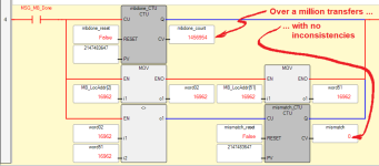
update ii: Below see an image of the the micro820 mismatch result with the dis_airt/en_airt enabled on the siemens side. Cut to the chase: Zero mismatches in over a a million modbus transactions with a functional equivalent to a lock in place, whereas there was roughly one mismatch per thousand transactions without the dis_airt/en_airt enabled.

I would expect @JesperMP's suggestion of using UMOVE_BLK would give similar results.

xxx.png
 

Similar Topics

Hello, I am looking for your suggestions for methodologies to sync process setpoints across a local HMI and remote SCADA system. Background...
Replies
18
Views
2,060
I'd like to hear how others have handled this kind of situation. I have four identical machines, each with a Red Lion CR3000 15" HMI and Beckhoff...
Replies
5
Views
2,505
TLDR; How to synchronize setpoint values between a local HMI and remote PLC connected by cellular modem, while preserving the most recently...
Replies
8
Views
4,100
I'm working on a design for a cutting machine. This system gets synchronized with the production line speed, Do the cutting and come back to the...
Replies
4
Views
2,549
Let's that I want to synchronize 2 digital outputs so the fist DO is ON for 600 ms and a soon it goes to OFF state the second will turn ON for 400...
Replies
1
Views
1,320
Back
Top Bottom