URGENT - High Speed Counters not working all of a sudden ML1400/Logix 500

well, as I said, the "bleeder resistor" idea is a long shot ... IF (that's a big IF) the power supply is indeed "floating" then the resistor might work ... but if that's NOT your problem then you need some kind of game plan as to how to proceed ... as near as I can tell from here, you have at least five logical areas in which to look for the problem – based on the assumption that the system DID indeed work at some point in the past ....

(1) something has changed in the PLC program ...
(2) something has changed in the PLC hardware ...
(3) something has changed in the system wiring ...
(4) something has changed in the power being supplied ...
(5) something has changed in the field instrumentation device ...

rather than simply saying that nothing has changed in any one of these, how much time/trouble would it take to actually TEST each of these items and then be able to conclusively eliminate them one-by-one from the list of potential candidates? ...
 
It does appear to be a voltage issue?

I checked one input, the resistor is fine 2.2k ohm

If I remove the wire from the input and touch the input terminal several times, my flow readings react, and totalizing works as it should.

I am wondering if somehow the entire HSC input bank went south... on two PLC's?

The code is fine. I am reading 12v across the pull up resistors, every input is high, no transitions no matter what the flowmeters are doing.

Damn

Well, if you can get the counts to go up by "pulsing" the input manually by touching the loose wire to the terminal, then the input card and PLC are fine. I would look for a broken sensor wire, or a bad sensor.
 
Well, if you can get the counts to go up by "pulsing" the input manually by touching the loose wire to the terminal, then the input card and PLC are fine. I would look for a broken sensor wire, or a bad sensor.

Yes, but all nine at the same time, across two controllers? This is why I'm perplexed. I uploaded old code, it did not help. I did not change any code anyhow...

Also, for a breif time last night, the flowmeters began to respond incorrecty, then seemed to 'settle down' and respond appropriately. I was ecstatic, until minutes later, they all ceased again. Sure sounds like an electrical issue at this point, be it controller or elsewhere.

Heading back to the site in 20 min!
 
1Mohm between GND and 24v- did not work.

Changing resistance of pull up resistor did not work.

I am going to the loop drawings and follow through from supply to instrument. I see 12v on all the flowmeter inputs, it's got to be it
 
Can you post the exact model of the flow meter? 12 Volts is ok as a high but to get the low signal the fflowmeter has to pull down to less than 1.5 volts. Can it do that? Or is the required ouput current from the flow meter close to its max current? I would bet that the output circuit of the flow meter is near max when pulling low and finally gives up until it's disconnected for a while. A larger value pull up resistor would have less voltage at the PLC input (ok as long as greater than 4.5 volts) and would be easier to drive to a low by the flow meter.
 
A ML1400 has an IQ series input, which can be either PNP or NPN, depending on whether the common for that group is Negative or Positive.
In my opinion, using NPN on that group would be a better than a pull up resistor.

If you are using high speed instead of normal inputs, you will be using inputs 0,1,2,3 , in one group
 
I love reading threads like this! This is why I come to this site. Of course, I'm not the one under the gun at the moment trying to solve the problem. But I'm still learning from the experience. I've been doing this a long time but I'm always interested in learning.

I'm always amazed at how knowledgeable and how helpful you guys are.

Thank you!
 
I have seen a similar problem. Differences were frequency was not high and the PLC was a Controlmicrosystems SCADAPack32.And the pulse came from a reed switch. The solution (not mine) was to lower the 24vdc supply to 9vdc. Which follows what bernie is saying.
 
Last edited:
A ML1400 has an IQ series input, which can be either PNP or NPN, depending on whether the common for that group is Negative or Positive.
In my opinion, using NPN on that group would be a better than a pull up resistor.

If you are using high speed instead of normal inputs, you will be using inputs 0,1,2,3 , in one group

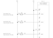
Yes, Gil. High speed inputs. All appropriately matched, and not using the non-HSC inputs in between. Loop drawing attached. (153 is 24+, 25 is 24v- and is also my discrete common) I will look into reversing the polarity, but I'm not quite sure, since it affects all my inputs, and that's a lot of wiring...

why, all of these decided to quit at the same time still has me reeling...

FM Inputs.jpg
 
Last edited:
err, I can just swap the common for one bank of inputs and not affect the rest of my inputs. Yes, I'll try this.
 
Something has got to be floating on you between the cabinet and the machine.

Do the sensors on the flowmeters have indicator lights on them? Are they flashing?

Interestingly enough the internal resistance of the inputs is about 2.5K Ohms. This explains the 12VDC. Depending on where the resistor is you may get this whether the flowmeter is connected to the controil cabinet or not. If the resistor is at the plc input or on the cabinet terminal strip the flowmeter isn't needed to get the 12VDC. If the resistor is on the flowmeter teminals than you at least know that 24VDC is getting to the flowmeters.

But you still wouldn't know is 24VDC comon is getting to the sensors. This wouldn't be required to get the 12VDC at the counter. but it would be required to get the flowmeter sensors to work.

The only thing I can think of that would cause all the sensors to "fail" the same way simultaneously is a loss of power or common.

Keith
 
Thanks Keith. The flowmeters do not have any indicators on them.

I've isolated one input, and can't get this one to work by reversing polarity, as in NPN.

I will call Omega, maybe all the sensors suffered a voltage spike and they just quit. Perhaps there is a way to test...

Thanks All, I hope to nail this one.
 
Another thing to try is to short the sensor output to common at the sensor and see if you get a count at the plc. That doesn't exactly nail a fault but it will at least tell you if the common at the sensors is all the way through to the plc cabinet.

Keith
 

Similar Topics

Heya everyone thanks for reading im stuck with a project im doing at work and cant find the problem :( I have an mitsubishi FX3U system connected...
Replies
3
Views
3,152
I have an old PLC (circa 2007) consisting of Telemecanique/Modicon/Schneider Electric devices. The system has developed errors and unfortunately...
Replies
2
Views
231
Guys, please help me with this urgently. We have Logic 5575 installed in hot n standby setup. For some reason, the primary now cannot sync with...
Replies
10
Views
380
I have DI module ICPCon M7024UD connect to my pc using COM3 MODBUS RTU and also RHT sensors are using MODBUS TCPIP.. The problem is, it cannot...
Replies
9
Views
1,669
Hi all, We are facing synching issues with redundancy module, where the Primary is ending up with disqualified secondary. Normally this would...
Replies
2
Views
625
Back
Top Bottom