WAGO PFC200 Modbus RTU

Join Date
Jul 2021
Location
Bulgaria
Posts
51
Hi,

For some time I have been struggling with establishing a MODBUS RTU communication between WAGO PFC200 750-8212 and a Sentera ACT-125-H damper valve for ventilation.

Damper Valve

Here is some info about the damper valve - it has input and holding register that are all unsigned integer (UINT) datatype. The following settings are used with respect to the MODBUS RTU - 9600 baudrate, 8 data bits, even parity, 1 stop bit.

Let me explain the wiring setup - from the controller enclosure one cable goes to the first damper valve and all the following damper valves are daisy chained. The cable is shielded with 4 cores - 24V DC and MODBUS RTU signals.

In the WAGO there is always a "response timeout error" and no information is read even though I only read one (1) holding register.

What I have tried is to calculate the time between the frames and the the between the characters in the frame. I got values in the milliseconds (ms) range and entered the values in the MODBUS RTU Master settings but the result is the same.

The damper valves work with a FATEK controller without any problem, they also work with a MODBUS to USB converter and a MODBUS Scanner program.

Another thing that I tried is to sniff what the WAGO and the damper valve send to each other. I used a MODBUS to USB converter connected in parallel to the WAGO. It seems that the WAGO is polling the correct date but the damper valves responds not what is expected. I compared the data with the data I sniffed from the setup with the FATEK controller and the MODBUS Scanner.

What would you suggest to do to investigate the problem further and hopefully find a way to resolve the problem?

Best Regards
Konstantin Kolev
 
Last edited:
Hi,I compared the data with the data I sniffed from the setup with the FATEK controller and the MODBUS Scanner

Can you post the sniffed requests from and responses to

  • the FATEK,
  • the MODBUS scanner (I assume this is on a PC), and
  • the WAGO?
The best format would be hexadecimal bytes.
 
Can you post the sniffed requests from and responses to

  • the FATEK,
  • the MODBUS scanner (I assume this is on a PC), and
  • the WAGO?
The best format would be hexadecimal bytes.
Hi,

Yes, the MODBUS Scanner is on a PC and I use Realterm for sniffing.

I made a spreadsheet with all the data.

Best Regards
Konstantin
 
Try reading holding register address 0. Sometimes devices are a 0 address offset, sometimes a 1 address offset.
Hi,

I tried reading holding register 0, the same result.

Then I tried reading holding register 40000 or 40001 as well, but still the same problem.

Best Regards
Konstantin
 
When the WAGO tried to read register 0, was the poll data data the same as when you tried to read register 1? If so, something is wrong on the WAGO side.

What do you see for poll data when you try to read register 2, register 3, etc.

The examples you posted are all valid Modbus transactions. The only difference is that the WAGO example is asking for and receiving data from a different address than the scanner and FATEK examples.
 
Is the valve Analogue / modulation input type (Ai1) configured for 0-10V, 4-20mA, or PWM?

I know this sounds like a distraction, but there is method to my madness ...
 
Never mind that bit about the input type; that was for input registers.

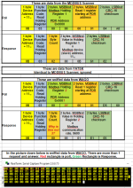
The valve is almost returning a correct response; see image below; see also here and here.

I have two questions:

  • What does the sniffed Response from the valve to the Wago look like when you duplicate the sniffed Poll from the Modbus scanner i.e. with a 0x00 in the fourth byte of the poll (see red digits in image below)?
  • What does the sniffed Response from the valve to the Modbus Scanner look like when you duplicate the sniffed Poll from the Wago i.e. with a 0x01 in the fourth byte of the poll (see red digits in image below)?
Untitled.png
 
Last edited:
Have you rebooted PLC after serial changes?
I assume that this is RS485 and not RS232. Is there end resistor 12-150 ohm on both sides of bus?


Also sometimes RS485 biasing or RS485 isolator is needed for some PLCs. Phoenix have active resistor for RS485 (2702636) and repeater/isolator (2744429).
 
The problem is most likely where @Lare has suggested i.e. in the termination resistors (or lack thereof); in any even it is almost certainly in the wiring from the valve to the Wago, even though it seems to work with the Modbus scanner and the FATEK.

TL;DR

The hardware is dropping bits.

If you check the CRC-16s, the final response, from the valve to the Wago, is
0B 03 00 00 01 E1 05
and, assuming the first five bytes are correct, that should have ended with a different CRC-16 i.e. 40 45.

However, if we change that third byte, 00, to 02, which would be the correct value for the length, then the CRC-16 would be E1 85, which is only two bits different over the entire message from what was sniffed.

Looking further down into the RealTerm image, on the second and third line, we see the Poll
0B 03 00 00 00 01 84 A0
which is exactly the same as the Polls from the Modbus scanner and the FATEK, but the response is
0B 01 02 00 02 61 82
which should have a different CRC-16 (A0 3C), but the interesting things in this case are

  1. that 61 82 CRC-16 is the same as the Responses to those Polls from Modbus scanner and the FATEK, and
  2. The Function Code in the valve's Response is 01, not 03, which it should have been to match the Poll. So if we
    1. flip the single 2-bit (bit 1) of that second byte's 01 so the byte value changes to a 03,
    2. assume the third and fourth bytes' 02 (length) and 00 (high byte of 16-bit integer) are correct,
    3. flip the single 8-bit (bit 3) and 1-bit (bit 0) of that fifth bit so the byte value changes to a 0B,
    4. assume the final two bytes (CRC-16) are correct,
    5. then the message would be correct.
The result of dropping a few bits like this is that the Response read by the Wago is not going to have a valid CRC-16, which is almost one reason for the Wago to reject those responses; another might be if the device slave address or the function code in the Response are wrong - that could be a reason for a timeout (Wago expects to get a 03 Function Code response from device ID 0B, and instead reads a 01 Function Code response from device ID 0B.

The system is dropping bits.
 
Hi,

Let me tell you what I have tried and what has been achieved these days.

First I tried adding biasing resistors of 1k ohms to 5V and GND but the result was the same - none of the valves was accepted by the WAGO controller. I added 500 ohms biasing resistors as well but still nothing. Then I disconnected the biasing resistor.

Then I decided to disconnect all of the valves but the first one - address 11. And surprisingly there was communication between the valve and the WAGO. I started connecting the valves to the bus one by one. Valve 12 was also successfully communicating with the WAGO. But when I connected valve 13, something happens and the communication was broken.

After wondering for quite some time what I have not tried yet, my colleague proposed to remove the shielding that is connected on the WAGO side to 0V on the 24V power supply. The shielding is daisy chained in each valves where on the last one the shielding is removed. Basically the shielding is connected only on the WAGO side.
When the shielding was removed, valve 13 was online and working. Afterwards I connected valve 14 to the bus and it worked flawlessly. And valve 15 was connected to the bus but the WAGO was not recognizing it.

But for some reason, after I had tried more tricks, valves 11 and 12 were lost while valves 13,14 and 15 were online and working flawlessly.
In respect to the termination resistors - I had a termination resistor at valve 15 but it made the situation worse, therefore I removed it. I only had a termination resistor at the WAGO side.

I decided to connect back the biasing resistors of 1k ohms to 5V and GND. The communication improved and valve 11 was online and working, the only valve that was not online was valve 12. I also played with the internal termination resistor in the valve.

I added error reading bits in WAGO on all of the valve and the error on valve 12 was RESPONSE_TIMEOUT or INVALID_CRC.

All of this happened yesterday.

Today, my colleague proposed to connect the valve to a separate power supply. We did that and valve 12 along with all the other valves are online now and working flawlessly. The reason is that with the FATEK the valves and the controller are on separate power supplies. The FATEK controller is 220V AC input and perhaps has a 24V DC converter inside it. Therefore the valves and the communication are on separate power supplies.

I do not know what will happen if I remove the biasing resistors now but I will leave it as it is since it is working now. There is no termination on the end of the bus as well, the termination is only at the WAGO side. The shielding is not connected for now.

I hope this explanation and this topic help someone else in the future who has similar problem with MODBUS RTU.

Best Regards
Konstantin Kolev
 
As communications are good if you remove ground, the problem is certainly on ground looping and noise on RS485 signal.
Adding RS485 isolator between wago and valves probably removes problem (like phoenix unit which I earlier mentioned).
 
Hi,

These days I have been trying to optimize and make my program more readable but I am struggling with one little problem where I need a small trick to accomplish my goal.

There are 8 damper valves for ventilation and 6 energymeters that are connected to the fieldbus now.

Let me explain what the problem is:

I created a structure for the Modbus RTU raw data which contains the same variables and arrays as the ones I defined in the Modbus RTU device configurator.

The task is to assign this structure, which is a structure created from the WAGO, to my structure that will have multiple instances - one for each device. But I get an error that the system type Modbus RTU structure of type "typEnergymeter_1_rtu" is not equal to my type of structure "energymeter_raw_data_struct".

The data type "typEnergymeter_1_rtu" is unique and created by the WAGO system for each of the Modbus RTU devices i.e. the Modbus structure for my Energymeter_2 is of "typEnergymeter_2_rtu" data type and so on. It follows the device names when creating the structure type.

The Modbus structure itself is called Energymeter_1_rtu and Energymeter_2_rtu and so on. All of the raw data that is read and written to the Modbus device is stored there.

I can assign individual elements of the system Modbus structure to my structure but not assign them as a whole structure type.

Best Regards
Konstantin Kolev
 
Hi

These days I got another small problem with my precious damper valves.

As we added 3 more valves to the bus, we now have 8 damper valves in total and 6 energymeters on the same bus line.

Last damper valve on the bus is working and I can see it in the WAGO PFC200 but for some reason the two new valves before the last one cannot be seen in the WAGO PFC200.

I connected my laptop via MODBUS to USB converter to each of the not working valves and tried polling with CAS Scanner. The valves are moving i.e. they can receive a command but when I try to read Input or Holding Register I get the error in the attached picture.

Code:
mb_responce_code=-8 - MB_RESPONCE_UNKNOWN

But since the last damper valve on the daisy chain is working there should be no problem with the bus line.

What do you think is the reason for this ridiculous situation?

Best Regards
Konstantin Kolev

Modbus Error.png
 

Similar Topics

Is there any main difference between PFC200 and PFC100? Is that so then, please elaborate. Thank you
Replies
1
Views
1,845
Hi! I've bought WAGO PFC200 controller to automate my smart home installation. After that I've noticed, that I also need to buy e!****PIT or...
Replies
1
Views
2,873
Good day, I've been browsing this forum for 2 years now, but this will be my first post. I have device with USB serial output. I would like to...
Replies
8
Views
2,782
Hello, I am in possession of a WAGO PFC 200 750-8216 which I was successfully able to set up as a Modbus RTU Master to a slave device using...
Replies
0
Views
87
I have a project to setup base programs across multiple PLC platforms that can be used for Modbus communications to various sensors that have...
Replies
0
Views
124
Back
Top Bottom