PD vs PI tuning for a pid loop

I think you should do a series and post it on youtube.
I enjoy watching the series done by Ron Beaufort and Archie.
It allows me to view them when I have the time available, and they are nicely done.

Thanks again Peter, for sharing.....I know you have a busy schedule......
:site:
 
Peter,

Have you considered writing in to Control Engineering in response to that article?
You responses definitely merit at least a small column.
 
PLCRookie said:
I think you should do a series and post it on youtube.
I have made videos but they are product based and I like to make them in HD quality, about 1280x800. I can make youtube videos but youtube doesn't have the resolution that I like. I want people to be able to clearly see the numbers on the screen. If I made a youtube video I would need to make extensive use of the zoom in and out feature.

Making product videos is easy since I am trying to explain what can be done but not how it is done inside the controller. Making educational videos is tricky, especially in the area of control. There aren't too many people that understand Laplace transforms or differential equations so they would be lost right at the start. When teaching a class or doing a webinar I can tell how advanced the class is and adjust the the class level. Actually, I don't like webinars that much either because I can't see the expression on the fasces. I must rely on the questions to find out whether I am getting through.

kdcui said:
Peter,
Have you considered writing in to Control Engineering in response to that article?
You responses definitely merit at least a small column.
No, my response is above. It will probably be read here as much as in control engineering magazine.

My comments on the article above are probably meaningless to most people if one doesn't understand the concept of poles and pole placement or linear quadratic control etc. In my post above the only thing I think the average person can really relate to is that the PI controller can't do a good job on tuning a mass on a spring because there is no damping. I think people can have an intuitive feel for that but at this point you guys are just taking my word for it that there should be one controller gain, not counting the integrator, for every open loop pole. I can show why with mathematics and graphs but I think most people would get lost in the math.

Meanwhile, do a search for some the threads labeled "Advanced Control" that were started by either me or Pandiani. If you have questions you can resurrect the old thread by asking a question.
 
Hello,
Peter explained it well, as always.
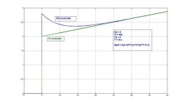
Just want to add a little bit to derivative component story. Like I said, I use derivative component when dealing with controlling level in tanks. It is because tank itself is an integrator (integrating process). In such cases, derivative component can indeed improve the response. The basic difference between PI and PID controller is represented in the attached picture which shows step responses. You can see that derivative component changes in step response.
In level control, derivative component can indeed improve the response since it acts as damping element. Everything depends of an actual application, but my personal rule of thumb is to try with derivative component every time when operator says "It would be good if this valve can begin closing (opening) earlier if the level is falling (rising)..."

My personal approach is to use PI and then if the process is integrating to try with D component to reduce the overshoot and also reduce the area of control error function (SP - PV).

Regards,
Pandiani

PID step response.jpg
 
Great Thread!


Basic points that that I have found useful:

1. P-Term (Proportional band/Proportional gain) is by far the most critical parameter and it is the amount added (or subtracted) to the control output based on the current SP/PV error. P-Only control assumes that there is a fixed ratio between the degree of PV response that can be expected for and given change in CV. In a perfect world, where there is always the immediate process response and exact same amount of PV change resulting from a CV output change, P-only process control is all that is needed.

2. I-Term (Integra Time Constant/Reset Rate/Integral Gain) is an amount added (or subtracted) to the P-term output over a time period that is based on the sum of the PV/SP errors. The Integral term is the most effective parameter in being able to enhance P-only control to achieve a faster "stable" response to a SP/PV error. For most process control applications where there is minimal "latent energy" in the system you should find PI control to be sufficient.

3. D-Term (Time Constant/Derivative Gain) is the amount removed (or added) from the P-Term (or PI-Term) output that is based on the rate of change to the SP/SV error. Many publications reference process response speed as the most important consideration when deciding when the D-term should be used. They often blindly reference response speed in seconds and even minutes. In actuality speed needs to be considered in a relative frame that is more dependent on how long it takes the measured PV to reach "steady state" in response to a CV change. It is true that using the D-term will have little to no positive impact in a process where there is a minimal (and repeatable) time lag between when a CV output change is made and the "full" PV response is achieved. It is also true that the use of the D-Term is ineffective when the SP/PV error can change directions within a few controller scans. The D-Term is very effective for processes where there is a significant amount of "latent energy" or “mechanical inertia” in the controlling system (i.e. heaters and mechanical motion) or when the process is very sensitive to SP overshoot. Using the D-Term in a process not requiring its use will result in slower recovery to SP and overall poorer SP control.

4. Simple PID control assumes that the systems PV response to a CV change is close to a linear function over the extents of the normal process range. Simply stated - for any given CV change there will be close to the same degree of PV response regardless of what the current CV value is. The more the PV response to CV change ratio varies over the normal process range from a linear function the more difficult it is to achieve optimum control with simple PID control. I know that I have spent hours of frustration trying to tune a loop where the control application used a poorly sized centrifugal pump or ball valve as the controlling device. In these examples the ratio of PV response to a CV change is not very linear from a 0 to 100% CV output - a 10 point increase to CV output when the current CV is at 10 will not achieve the same magnitude of PV change as when the 10 point change occurs when the current CV is at 50. There are many "advanced" PID controllers that can use a multitude of different "fuzzy logic" approaches to overcome the failings of the "simple" PID controller. The rule must be – KNOW YOUR PROCESS!

5. Understand your controller - the P, I, and D terms are defined differently by manufacturer and device. For example the P-Term can stand for Proportional Band or Proportional Gain and the I-Term may be a Time Constant, a Reset Rate, or Integral Gain. The basic functions are similar, but the value you enter can represent a variable in a totally different mathematical equation. I know I had trouble understanding the huge difference in the PID values when looking at PID values in similar process’s that used different controllers.

6. Always use some form of chart recorder when tuning a PID loop. At the very least chart the PV. I have also found tracking the CV to be helpful when coming in blind to a new process. The PV response curve is the only way to gage the effectiveness of a PID Term change. I find it utterly impossible to optimize a PID loop without the chart recorder.

7. Decide what type of control is most appropriate for the application, P, PI, PD, PID, or Advanced PID. Always start tuning with the P-Term while the other parameters are set to a minimum number. The typical response for P-Only control will be a periodic oscillation above and below SP when the P-Term is too large or a failure to reach SP when the P-Term is too low. I have found the optimum P value to be the point at which the 1st sign of oscillation is seen. Once a comfortable P-value is determined then move to I (PI control) or D (PD control), Starting points should be low values and be incremented up slowly until the response curve shows the quickest response with an acceptable level of overshoot. Complete the tuning by adding D in PID control. Always monitor your process in both steady state and in response to the maximum level of expected PV change.

Keep the controls as simple as possible. Added sophistication leads to longer set-up times when a process changes. Use only what is needed to get the job done
 
I am putting you on the spot.

Bill Wheeler said:
Great Thread!
The Integral term is the most effective parameter in being able to enhance P-only control to achieve a faster "stable" response to a SP/PV error.
Why not simply use more P gain?
I thought adding the integrator introduced 90 degrees of phase lag. It certainly introduces another pole.

For most process control applications where there is minimal "latent energy" in the system you should find PI control to be sufficient.
What about the mass on the spring?

It is true that using the D-term will have little to no positive impact in a process where there is a minimal (and repeatable) time lag between when a CV output change is made and the "full" PV response is achieved.
Again, what about the mass on the spring?

It is also true that the use of the D-Term is ineffective when the SP/PV error can change directions within a few controller scans.
???

The D-Term is very effective for processes where there is a significant amount of "latent energy" or “mechanical inertia” in the controlling system (i.e. heaters and mechanical motion) or when the process is very sensitive to SP overshoot.
It depends upon the number of poles. You totally ignored or misinterpreted what I said.

I know that I have spent hours of frustration trying to tune a loop where the control application used a poorly sized centrifugal pump or ball valve as the controlling device. In these examples the ratio of PV response to a CV change is not very linear from a 0 to 100% CV output - a 10 point increase to CV output when the current CV is at 10 will not achieve the same magnitude of PV change as when the 10 point change occurs when the current CV is at 50. There are many "advanced" PID controllers that can use a multitude of different "fuzzy logic" approaches to overcome the failings of the "simple" PID controller. The rule must be – KNOW YOUR
This is what happens when the mechanical designers save a few buck on the valves and waste far more in the control guys time plus the fact the system will never run as well as it could and this costs money every minute.
I am actually working on an auto tuning for non-linear valves now.

Always use some form of chart recorder when tuning a PID loop. At the very least chart the PV. I have also found tracking the CV to be helpful when coming in blind to a new process. The PV response curve is the only way to gage the effectiveness of a PID Term change. I find it utterly impossible to optimize a PID loop without the chart recorder.[/FONT]
Yes, but one should graph both PV AND the CV. Then one can calculate the PV as a function of CV which is the first step to auto tuning.

Decide what type of control is most appropriate for the application, P, PI, PD, PID, or Advanced PID.
How?

Always start tuning with the P-Term while the other parameters are set to a minimum number. The typical response for P-Only control will be a periodic oscillation above and below SP when the P-Term is too large or a failure to reach SP when the P-Term is too low. I have found the optimum P value to be the point at which the 1st sign of oscillation is seen.
These are the kind of statements I object to. I am very disappointed because what I said above was not understood.
Again, think of the mass on the spring. It will oscillate on its own and adding any P gain will make it worse. There is no or little damping!!!!! So what would you add first???? Please say derivative gain.

I object to Bill Wheeler's post for the same reason I objected to the Control Engineering article. There are too many statements that aren't qualified.

BTW, don't think the mass on the spring is unrealistic. Hydraulic systems can be roughly modeled as a mass between two springs. Sure there is a little friction but that is often the problem. There is only a little friction relative to the mass so the damping factor is quite low.

Another example is a small DC motor in torque control with a mass spinning freely on the end of the shaft. I have such a system. The damping on this system is quite low because the mass is large compared the friction. If I turned up the P gain a little it will oscillate without stopping. I like to demonstrate the effect of the derivative gain by turning all gains off and letting the students turn the shaft. They find it turns and spins freely. Then as I increase the derivative gain ONLY the students can feel the effect. It is like some is in grabbing the shaft and trying to keep it from turning. Eventually the D term is up so high that the quantizing effects do to the low resolution make the turning feel rough instead of smooth. At this point the derivative gain is too high and it should be backed off. Now one can increase the P gain to very high levels. The P gain can be increased to MUCH higher than if one simply adjusts the P gain first until it oscillates without the derivative gain.

I am not making this stuff up. This is not an opinion or something that I am repeating from someone else and without proof. I have hundreds of Mathcad files showing how to tune many different types of systems many different types of ways and showing the response. I have proof and the math to back it up. I have enough examples where it is easy for me to find examples that are "exceptions" like the mass on a spring.
 
Hello i am knew to the forums but Mr Nachtwey moved me enough to say sir your words have meaning and conviction. I relize now i no so little about this subject respect Mr Nachtway

ps any time you want to spill the beans on PID Loop I will listen
 
Hello i am knew to the forums but Mr Nachtwey moved me enough to say sir your words have meaning and conviction. I relize now i no so little about this subject respect Mr Nachtway

ps any time you want to spill the beans on PID Loop I will listen
There are too many beans catch them all without knowing Laplace transforms and having a good CAS ( computer algebra system ) like wxMaxima. Matlab or Scilab would help too. It took me many years to learn.
 
Maybe, it would be good to start another thread or continue this one about control of mass on a spring. Objective would be to try to find best response using PI only controller and then PID and to discuss about contribution of the derivative component.
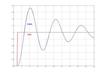
We could start by simple model Gp = 1/(s^2+0.2s+1), where damping ratio is much lower than 1. Some specifications can be stated like overshoot less than 20% and/or settling time less than 10sec or something like that.
It would be interesting to see and compare PI and PID solving this problem.
Anybody interested?
Sure, I almost have it done now.
I need to find a way of computing the PI gains. I will use the IAE, integrated time absolute error method. This methods tries all combinations of PI gains the yield the minimum sum of absolute errors. I need to cut an paste that from another work sheet.
Here is a good solution for critically damped control.
http://www.deltamotion.com/peter/Mathcad/Mathcad - T0C1 MassOnASpring-PID.pdf
If I make lambda bigger the response will be a little faster but the have realistic limits on what the output can be so increasing the gains only causes the controller to saturate the system. Saturation occurs when the green line, the control output or force, reaches 100%. Usually this happens when there is a design flaw and the mechanical guys didn't design the system properly to move as fast as desired.
 
Last edited:
No, Peter, you'll spoil the fun... Please don't post anything for now. The main goal is to have productive discussion with other members. I think that this "mass on a spring" is an excellent example to demonstrate how D component is not always Danger or Disaster....

In the attachment is given a typical step response of mass on a spring system. I have assumed the following transfer function (1/(s^2+0.2s+1). As you can see damping factor is very small and oscillations are significant. Objective is to design PI or PID controller that would provide minimum overshoot (less than 10% or smaller) with settling time, let's say smaller than 5 sec.

Spring_mass.jpg
 
Last edited:
Why would anyone bother when Peter is always there? :)
Peter, What are PI controller parameters for IAE performance index? I have got Kp = 0.62 and Ti = 6.163s with the following PI form: Gpi = Kp+1/(Ti*s)
 
Last edited:
Hello,
I prefer using PD controller in level loops. The biggest strength of PD controller is in case if you're controlling level in some tank with motorized control valve. In that case, you'll have double integrator in the loop and problems with overshoot. PD can be used succesfully to provide good response.
I suggest you reading posted links ablut D part of the PID controller. If PV doesn't contain noise (properly filtered), then D can be your friend.
Like I said, I'm using D almost exclusively in level control(integrating process) and the structure really depends on actual application.

Regards,
Pandiani
hi m doing my FYP regarding PID control of inverted pendulum.m facing problems now of having analoge interface with AB SLC 5/03.can u help me?if u can plz come online at yahoo [email protected] online here right now
 

Similar Topics

Hello, I am attempting to tune a PID loop on a process. The process involves a valve with electronic actuator that has quite a high deadband...
Replies
10
Views
2,206
Hello Everyone, I have a fast PID loop that I was having issues with tuning it. - The CV is a sliding stem valve - The PV is a High pressure...
Replies
36
Views
24,091
Hi all, splitting out from this thread because it's a somewhat different question to the original. I have to migrate some code from a Micrologix...
Replies
17
Views
4,141
Long time listener, first time caller. I have a Micro850 PLC controlling the temperature in seven fermentation vessels at a local brewery. Each...
Replies
2
Views
2,616
I am using PID instruction in RS Logix 5000 with independent equation. I am confused about its tuning. Please somebody explain under listed...
Replies
1
Views
4,940
Back
Top Bottom