PD vs PI tuning for a pid loop

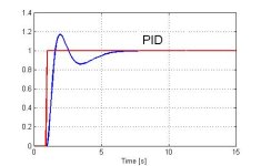
Pandi and I spent about an hour trying to figure out a better solution for the PI gains and we couldn't find any. Pandiani used Matlab and I used Mathcad in our effort to find the best PI solution. There is no combination of PI gains that can provide a response that doesn't overshoot and oscillate for a while. After all of that effort the PI solution is no where close to my PID solution. You can see the PID solution has much faster response and doesn't overshoot. That is because the PID gains are much higher than the PI gains and yet still don't oscillate or overshoot.
 
Advanced Control mass on a spring

Like Peter said, we spent quite amount of time in our regular Skype session trying to tune PI controller to solve mass on a spring control problem.
I used Matlab built in PI/PID optimizer and the results are:
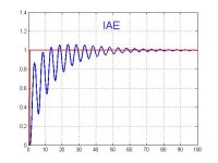
- for IAE (Integral Absolute Error) performance index, PI controller is: Gpi(s)=0.62+0.162/s. So, proportional gain is 0.62 and integral gain is 0.1622.
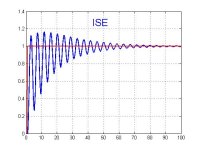
- for ISE (Integral Squared Error) performance index, PI controller is: Gpi(s)=1.18+0.218/s.

Step responses are shown in attached files.

As you can see, the response is very oscillatory with long settling time and PI controller just can't solve the problem.

In his pdf file, Peter showed how to calculate PID gains and simulate the system. I used the pole placement method, too.
However, I have used realistic derivator (with smoothing filter) with the following transfer function:
Gpid(s) = Kp + 1/(Ti*s) + Td*s/(T1*s+1). Objective is to find Kp, Ti Td and T1.
Since system's transfer function is 1/(s^2+0.2s+1), overall transfer function is: Gw = Gpid*G/(1+Gpid*G)
Gw =
((5*Kp*s^2*Ti+5*s)*T1+(5*s^2*Td+5*Kp*s)*Ti+5) / (((5*s^4+s^3+(5*Kp+5)*s^2)*Ti+5*s)*T1+(5*s^2*Td+5*s^3+s^2+(5*Kp+5)*s)*Ti+5)

And the characteristic equation is: Like Peter said, we spent quite amount of time in our regular Skype session trying to tune PI controller to solve mass on a spring control problem.
I used Matlab built in PI/PID optimizer and the results are:
- for IAE (Integral Absolute Error) performance index, PI controller is: Gpi(s)=0.62+0.162/s. So, proportional gain is 0.62 and integral gain is 0.1622.
- for ISE (Integral Squared Error) performance index, PI controller is: Gpi(s)=1.18+0.218/s.

Step responses are shown in attached files.

As you can see, the response is very oscillatory with long settling time and PI controller just can't solve the problem.

In his pdf file, Peter showed how to calculate PID gains and simulate the system. I used the pole placement method, too.
However, I have used realistic derivator (with smoothing filter) with the following transfer function:
Gpid(s) = Kp + 1/(Ti*s) + Td*s/(T1*s+1). Objective is to find Kp, Ti Td and T1.
Since system's transfer function is 1/(s^2+0.2s+1), overall transfer function is: Gw = Gpid*G/(1+Gpid*G)
Gw =
((5*Kp*s^2*Ti+5*s)*T1+(5*s^2*Td+5*Kp*s)*Ti+5) / (((5*s^4+s^3+(5*Kp+5)*s^2)*Ti+5*s)*T1+(5*s^2*Td+5*s^3+s^2+(5*Kp+5)*s)*Ti+5)

And the c
haracteristic equation is:
s^4+(1/5+1/T1)*s^3+((5*Kp+5)*T1*Ti+5*Td*Ti+Ti)*s^2/(5*T1*Ti)+ (5*T1+(5*Kp+5)*Ti)*s/(5*T1*Ti)+1/(T1*Ti)


And the desired characteristic equation is (s+a)^4. I have chosen a = 2 and thus have s^4+8*s^3+24*s^2+32*s+16.


Comparing last two equations, we have the following set of equations:
1/(T1*Ti) = 16
1/Ti+(Kp+1)/T1 = 32
Kp+1+Td/T1+1/(5*T1)=24
1/5+1/T1 = 8


Solution of the previous set of equations is:
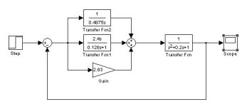
T1 = 0.128s
Ti = 0.4875s
Td = 2.382s
Kp = 2.83


PID controller structure is given in attached picture "PID.jpg" and response is given in the picture "PID_response.jpg".

As you can see this solution leads to overshoot and this is due to zeros in overall transfer function that were introduced by PID controller.
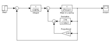
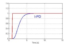
If overshoot cannot be tolerated, then I-PD structure is used (most commercial PID controllers that comes in standard software packages are not that flexible and don't allow changes in controller structure but still its good to know). I-PD is different than PID in a way that proportional and derivative components are in feedback path only. The structure of I-PD controller is given in picture "I-PD.jpg" and the response is presented in "I-PD_response".jpg


PI_IAE.jpg PI_ISE.jpg PID.jpg PID_response.jpg I-PD.jpg
 
Last edited:
And here is the response of I-PD controller structure.

That's all for tonight folks. I hope the original thread starter is happy.

Best regards,
Pandiani

I-PD_response.jpg
 
I updated my worksheet

http://www.deltamotion.com/peter/Mathcad/Mathcad - T0C1 MassOnASpring-PID.pdf
What I posted this morning was a similar worksheet that I modified. This updated worksheet has my PI solution. It is similar to Pandiani's solution and it oscillates like Pandiani's does. Pandiani and I have software that can try hundreds combinations of PI gains that minimize the error between the set point and the process value or target and actual position in this case. This makes finding gains easy as long as the system is known.

One should notice that my solution applies up to 100 Newtons of force to move the mass as quickly as it does. I limited the force to 100 Newtons. Pandiani's problem has a spring constant of 1N/m so to hold the mass at 1 meter required 1 Newton of force. The PI control adds no damping so it cannot apply much more than the 1 Newton of force without oscillating wildly.
 
To Peter

Peter,

I didn’t intend to ruffle your feathers - By far your expertise on this subject far exceeds mine. My intent was to discuss what I have found to be effective for “simple” PID control spanning a broad cross section of applications. I think that what I stated has merit for many applications.

Your example of a mass on a spring is an excellent way of describing a process where there is significant energy stored in the controlling equipment, that when released, results in control error. Maybe my choice of words, “latent energy” and “mechanical inertia”, were not easily understood. The intent was to point out that the D-term is effective when dealing with applications where not all the energy applied to the CV is immediately transmitted to the PV. This is the case when describing your mass on the spring example where the force that went to initially move a mass is transferred as potential energy to the spring - Motion of the mass will continue until the energy in the spring is dissipated through friction. The D-term application applies also to any mechanical motion systems where the inertia (amount of resistance of a mass to a change in its velocity) can result in a significant error, and also applies to heating applications where a heating element represents a large thermal mass that continues to dissipate heat after power to the element is removed (Latent Heat). In broad terms I would say that “system inertia” is a fitting term that can be used to encompass all three of these conditions.

I have found that the simplest approach to meet the objective is always the best way. From my experience, the more complicated the control scheme is the more inflexible it becomes to process change. When I look at the variety of PID loops found in my factory, by far the overwhelming majority of the process control applications have small “inertial” qualities where P and I provide the most impact on a process. I’ve seen too many control issues resulting from the D-Term being applied for no other reasons than that it was there or the D-Term was used to compensate for too high I and/or P values. I personally have never had hands on experience with a process where the “inertial” qualities of the process ranked high enough where PD-only control was the most appropriate control method (though you have given great scenarios where this type of control can be the most effective). The criteria I have used to select the method of control in “general terms” are:
1. I select P-Only when the PV response to a CV change is close to a linear function over the entire normal process range, and the measured PV response to the full CV change is very quick. An example where P-Only control works is flow control of a non-compressible fluid where the control valve’s CV coefficient is nearly linear from closed to fully open (i.e. v-ball design).
2. I select PI control when the control system “inertia” is smaller than the allowable SP overshoot; the process requires a fast response to a SP/PV error; and the process is tolerant to a repeatable level of SP overshoot. An example would be in-line heating application for a gas or liquid where the goal is to heat a fluid stream as quickly as possible and where a level of SP overshoot has negligible impact on the end product.
3. I select PID control when the process goal is to minimize the recovery time of a SP error while also minimizing the SP overshoot resulting from system inertia or latent energy. An example would be an oven application where the desired goal is to recover to set point as quickly as possible while minimizing the overshoot caused by latent heat at the heating source.
4. As I stated, I never have had a need for PD-Only control in the past, but I do understand the concept and power of this method. You have made your point very clear.
5. I term “Advanced PID” control as the multitude of methods that can be applied to address the shortcomings of a simple stand-alone PID controller that only has a single PV input and CV output and only has the variables of P, I, and D to work with. The techniques I’m talking about include such things as “cascade control”, “feed forward” and “feed back” methods, and also methods that allow for implementing functions to condition either the PV measurement or the CV output in order to compensate for a non-linear PV response to a CV change. I’ll leave further discussion of these control concepts to the experts.

If you were to google “PID Loop Tuning Methods” you’ll find a multitude of approaches ranging from empirical methods to the age-old manual Ziegler-Nichols method (basically make a change and observe the response). Is there one way that works in every application? – No I don’t think so. Loop tuning is a time consuming task that requires you to be able to detect the results of a variable change and be able to decipher whether the change was positive or negative. If this process is done manually then I see no other way than to look at one variable at a time starting with the most significant variable and moving down to the least significant.

Again I apologize if I have offended you – I just thought I would pop in and share. I have always taken the approach of “always the student and mentor and never the master”. I have found those that overly display their mastery of a subject tend to have a block in the grey matter between their ears. I’m not accusing you of this fault; you seem to be someone that takes pleasure in being the mentor and not the closed-minded master. There is one thing that I have learned to do is listen very closely to every idea and break everything down and find the associative links of truth. I hope that I have expressed myself well enough so that others can break the words down so that they can grasp a concept helpful to their own endeavors.
 
I am not offended

It is the general statements made right after I made my post about the general statements made in the Control Engineering magazine. I am thinking why bother if people don't understand that each system is different.

I have stumped many with the mass on a spring example. It may not be fair and I know that most of you don't tune a system that looks like a mass on a spring but still one must be careful when giving advice that you know what their system is and what form of PID they are using.

Bill Wheeler said:
PID control spanning a broad cross section of applications. I think that what I stated has merit for many
Yes, but what about those where your advice doesn't apply and may be harmful?

You are right that the compressed spring has potential energy but the energy is transfer to the mass and the spring at the same time. The force that compresses the spring also pushes and accelerates the mass. Also the potential energy in the spring only returns to zero when the spring is returns to its uncompressed or stretched state. It has nothing to do with friction. The energy in a spring is (k*x^2)/2 assuming spring constant k truly a constant. I don't see a friction term in there. If you think about it the more friction the more force that is required to overcome the friction so the spring compresses more and has more potential energy.

The D-term application applies also to any mechanical motion systems where the inertia (amount of resistance of a mass to a change in its velocity) can result in a significant error, and also applies to heating applications where a heating element represents a large thermal mass that continues to dissipate heat after power to the element is removed (Latent Heat). In broad terms I would say that “system inertia” is a fitting term that can be used to encompass all three of these conditions.
Another general statement to which I can find a simple exception.
A simple motor system with a time constant for the inertia K/(tau*s+1) does not need a derivative gain for velocity control. It doesn't matter how big the inertia is. The system may need power but not a derivative gain.
However for position control a derivative gain is required because the open loop system how has an extra pole for integrating velocity to position.

I’ve seen too many control issues resulting from the D-Term being applied for no other reasons than that it was there or the D-Term was used to compensate for too high I and/or P values.
That is a good enough reason if the error needs to be reduced by using higher gains.

I select P-Only when the PV response to a CV change is close to a linear function over the entire normal process range, and the measured PV response to the full CV change is very quick. An example where P-Only control works is flow control of a non-compressible fluid where the control valve’s CV coefficient is nearly linear from closed to fully open (i.e. v-ball design).
This is off topic but flow is proportional to the square root of the pressure drop so unless the pressure drop across the valve is constant.

P only gains don't work well unless the system is a type 1 or integrating system. There is always going to be an error while the SP is different from ambient or steady state for type 0 or non-integrating systems.

I select PI control when the control system “inertia” is smaller than the allowable SP overshoot; the process requires a fast response to a SP/PV error; and the process is tolerant to a repeatable level of SP overshoot. An example would be in-line heating application for a gas or liquid where the goal is to heat a fluid stream as quickly as possible and where a level of SP overshoot has negligible impact on the end product.
]
What about for a SOPDT system? A SOPDT system should have a derivative gain. A SOPDT system has one more pole than a FOPDT system and there should have one more gain. The system may tune OK without the derivative gain but the response will not be optimal.

I select PID control when the process goal is to minimize the recovery time of a SP error while also minimizing the SP overshoot resulting from system inertia or latent energy. An example would be an oven application where the desired goal is to recover to set point as quickly as possible while minimizing the overshoot caused by latent heat at the heating source.
It depends upon the number of poles in the open loop system, not whether it overshoots. I have said this before above.


Again I apologize if I have offended you – I just thought I would pop in and share.
I am not offended, I am just pointing out that you should know more about control theory, more about the other persons system and the form of PID they are using before offering advise. I believe you can get your systems going well enough. You need to know how different types of systems are tuned. There are type 0 ( non integrating ), type 1 ( integrating ). For both of these categories there are single pole or first order system and two pole ( second order systems ). The second order systems can be over damped, critically damped or under damped. Then you can add dead time to the mix for some systems. There are third order and higher systems. These can be nightmare systems to tune. You have to know what you are dealing with before giving advice.
 
I just ran across this. Excellent discussion and research by Peter and Pandiani. My only comment is that feedback control might be split into two applications - process control and servo-mechanism design. The first is usually focused on maintaining a setpoint with external disturbances ("line out" the plant) and the later is focused on following a rapidly changing setpoint. Servo-mechanism design often involves motorized positioners or hydraulic valves, which appears to be Peter's applications. The split is also along the training of ChE's and ME/EE's.

I think there are two reasons that strong derivative action is often used in servo-mechanism design. One is that the systems often have a lot of intertia - Bill's "latent energy" and Peter's "spring-mass". They agree on the need for strong D action.

The other reason is that the D action responds immediately to setpoint changes, assuming you take D of the error (PV-SV) and not just PV as some PLC blocks allow. This is feed-forward action on setpoint changes, which is the main disturbance in servo-mechanisms. Of course, as Peter says it is better to apply explicit feed-forward equations based on careful modeling or experiments. However, using D action is a simple "poor man's FFD" and the only practical approach in pre-computer days, which is likely why D action was common in servo-mechanism design.

As most people stated, there are no hard rules and there is always overlap. A batch process where the setpoint is scheduled is perhaps an example of "servo-mechanism control" in the process industries.
 
Last edited:
I think there are two reasons that strong derivative action is often used in servo-mechanism design. One is that the systems often have a lot of intertia - Bill's "latent energy" and Peter's "spring-mass". They agree on the need for strong D action.
Actually it depends on the number of poles in the system. The mass and spring problem requires a D term to add damping so that the closed loop transfer function is critically damped. The PID can be used to place all the closed loop poles on the negative real axis. As shown, a PI controller is short one gain and provides no damping.

The other reason is that the D action responds immediately to setpoint changes, assuming you take D of the error (PV-SV) and not just PV as some PLC blocks allow.
In motion control you almost always ramp the set point to avoid shock and exceeding the capabilities of the system and therefore staying under control. Turning the heaters on 100% on a temperature system doesn't moving or anything but may shock something if the material is subject to thermal stress.

Actually, I use the derivative term on the PV or actual position often. There are good reasons for doing so. One you just mentioned about not letting the control output go into saturation when there is a step change in the set point or target position. Another reason is that applying the D gain to the rate error introduces a zero that may and probably will cause over shoot when responding to a step change in the SP.

This is feed-forward action on setpoint changes, which is the main disturbance in servo-mechanisms.
No, feed forwards are dependent on the target position or SP and its derivatives only.

Of course, as Peter says it is better to apply explicit feed-forward equations based on careful modeling or experiments. However, using D action is a simple "poor man's FFD" and the only practical approach in pre-computer days, which is likely why D action was common in servo-mechanism design.
You are looking at this backwards. The D gain normall acts on the error in the first derivative or rate. The rate is often difficult to compute if the feed back resolution is poor, there is noise, or there is sample jitter.
Feed forwards are ideal and not subject to feed back problems.
Feed forwards are easy to implement.
If you have feed forwards implemented there may not be a need for the D gain unless disturbance rejection is a problem.
 
I think there are two reasons that strong derivative action is often used in servo-mechanism design. One is that the systems often have a lot of intertia - Bill's "latent energy" and Peter's "spring-mass". They agree on the need for strong D action.
I am not sure about the 'latent energy" comment. In the mass and spring system the D gain provides damping but damping isn't required in a temperature system. Still the D gain is often required to avoid over shoot when the controller gain is high to decrease rise time.

Actually whether a D gain is required depends on the number of open loop poles in the system.

The other reason is that the D action responds immediately to setpoint changes, assuming you take D of the error (PV-SV) and not just PV as some PLC blocks allow.
In motion control you almost always ramp the set point to avoid shock and exceeding the capabilities of the system and therefore staying under control. Turning the heaters on 100% on a temperature system doesn't moving or anything but may shock something if the material is subject to thermal stress.

I use the derivative term on the PV or actual position often. There are good reasons for doing so. One you just mentioned about not letting the control output go into saturation when there is a step change in the set point or target position. Another reason is that applying the D gain to the rate error introduces a zero that may and probably will cause over shoot when responding to a step change in the SP.

This is feed-forward action on setpoint changes, which is the main disturbance in servo-mechanisms.
No, feed forwards are dependent on the target position or SP and its derivatives only. The derivate gain is dependent on the rate of change in the PV or actual position.

Of course, as Peter says it is better to apply explicit feed-forward equations based on careful modeling or experiments. However, using D action is a simple "poor man's FFD" and the only practical approach in pre-computer days, which is likely why D action was common in servo-mechanism design.
It is easier to implement the feed forward than finding the rate of change in the PV or actual position.
 
Peter,

You mis-understood when I said "setpoint changes". I never meant to describe a sudden step change in setpoint. Indeed, in most servo-mechanisms the setpoint is a gradually changing voltage signal.

A classic servo is the old analog chart recorders that older readers recall. The input voltage to plot was the setpoint to a "pen position" controller (after signal conditioning). A motor moved the pen until a balancing voltage was located on the slidewire. The pen was jumpy if the slidewire was dirty.

Other examples of servos are "power steering" and similar "user amplifiers" (autos and aircraft) where the controller follows a mechanical setpoint input by the driver. Another is the common "dome-loaded pressure regulator" where the setpoint is the pressure applied to the dome. Indeed, most electronic amplifiers are servos.

When you say "feedforwards are dependant on ... the SP and its derivatives", it sounds like you recommend using the SP time derivative (i.e. D action) to apply feed-forward action, as suggested, so unsure why you start with "No,". Regardless, it worked for me in one PID application until I was able to develop better feed-forward equations that improved the control. The SP is normally a clean signal so its derivative isn't usually noisy.

Your approach of carefully modeling a system and developing optimum control algorithms, including feed-forward action (which is usually very effective) is ideal. However, that is usually only funded when developing a commercial product which will be cloned many times. Probably most readers work in an environment where they are responsible for tens or hundreds of control loops and barely have time to tune them, much less apply advanced analysis. If they can find a suitable solution by just varying the 3 PID tuning constants, that is enough. In many cases the controller may be a PID box that doesn't allow any user equations (unlike a PLC or PAC).

The above rant recalls a case where I used D action to greatly improve a controller. It was a PLC pressure control loop driving a hydraulic valve. It appeared the valve slewed one way or the other to a small voltage change, never reaching a steady position (no stem position inner loop). I decided the valve made the "plant" act as a pure integrator and thought the only way to beat an integrator is to apply strong derivative action. That quickly brought the loop into control and they have been running with that tuning since.

You will wonder why a more careful design approach wasn't used above. I was brought in because I was in an adjacent control room and they heard I knew about controls. They were flowing steam, trying to tune the loop in the new A-B system, which the rep. had helped them set up to replace an old 1950's analog system. First I heard of the project. They didn't even know the control direction, i.e. "does raising this voltage make the valve go open or shut?" Also, my first time looking at an A-B PID block (and even LD), but we got it semi working on the 3rd steam flow and optimum by the 5th blow. Good since the steam was expensive (>$10K). Anyway, a good example of the world many of us work in.
 

Similar Topics

Hello, I am attempting to tune a PID loop on a process. The process involves a valve with electronic actuator that has quite a high deadband...
Replies
10
Views
2,206
Hello Everyone, I have a fast PID loop that I was having issues with tuning it. - The CV is a sliding stem valve - The PV is a High pressure...
Replies
36
Views
24,091
Hi all, splitting out from this thread because it's a somewhat different question to the original. I have to migrate some code from a Micrologix...
Replies
17
Views
4,141
Long time listener, first time caller. I have a Micro850 PLC controlling the temperature in seven fermentation vessels at a local brewery. Each...
Replies
2
Views
2,616
I am using PID instruction in RS Logix 5000 with independent equation. I am confused about its tuning. Please somebody explain under listed...
Replies
1
Views
4,940
Back
Top Bottom