Rotary Encoder

I have done this on a travelling cut off saw, the pipe was continuously extruded while the cut off saw was at it's start position, when the length was reached the cut was initiated (start cut & travel at same speed as extruded pipe) and at the same time the counter was reset to start measuring the next length.
This seems almost the same as your application, so I think all you need once you have the counter programmed is to compare the set point with the counter, start the cut, reset the counter, the only caveats are you may need to add a little offset depending on the scan time of the PLC (only required if the speed of the extrusion is very high.
The one I did in the early 90's was actually a giant diamond encrusted circular saw, there was a calculation that took the size, shape, wall thickness of the extruded metal pipe (square/round) & calculated the cut rate based on the number of teeth etc. to get the most out of the life of the blade.
So....
Scale the high speed counter into mm for example if it was 100 pulses per mm divide the high speed counter by 100 & store this in a register (assuming +- 1mm tolerance).
Compare this register with the HMI Set point with a greater than or equal >= (do not use just an equals as if the count was greater by 1mm then it would not start the cycle this could happen if the scan time of the PLC was greater than the time it took the encoder to count the raw equivelent of 100 (1mm)). Some will say use interrupts but it could just happen, in the very unlikely scenario it would mean the extrusion would be 1mm longer or what ever the setting is, start the cut sequence & reset the high speed counter so that as the cutter travels with the extrusion it starts to count the next length.
 
I'm inclined to agree Peter, however, due to the costs of motion control especially in a retrofit it is unlikely this will be an option been there many times & often the cost is out of the scope of this sort of project.
It will also depend on the required accuracy expected, the OP needs to add more information to get responses that will work.
 
I don't usually rely on scaling length to counter pulses. If at all possible, at setup time, there would be a sensor, button (physical or HMI) to grab the start count then jog the material to position and grab the target count and calculate the length in pulses from that. I may convert to length units for display purpose but not for positioning. In one application I did this on the fly with two sensors, one at start and one at end. That was done with Siemens V4.1 which has the newer CTRL_HSC_EXT instruction and capture function; along with hardware interrupts.


What I would find challenging and interesting in the application in the OP, is synchronizing the knife with the conveyor as I've never done anything like that.
 
Multiplying by unity

Some people have no sense of proportion ;).

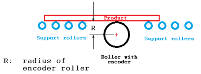
Here is one way to estimate the conversion of product linear motion to encoder counts.

Assumptions/Caveats


  • a process similar to this image:
xxx.png
  • No slippage between encoder roller and product
  • Everything is in the length same units, e.g. furlongs or cm or inches
What we know

  • R = radius of encoder roller, e.g. 6cm or 2.4inches
  • 2 π R linear motion = 1 circumference
    • π ~ 3.141569...
  • 1 circumference = 1 revolution (of rotation)
  • 1 revolution = 1024 (encoder) counts
  • When we multiply any quantity by unity (i.e. by 1.0), the result is the same as the original quantity.
Dividing each of those equations by its left-hand side yields several expressions that are equal to unity (i.e. equal to 1.0):

E.g. starting with [2 π R linear motion = 1 circumference]
Code:
[INDENT]2 π R linear motion = 1 circumference
------------------- = ----------------
2 π R linear motion = 2 π R linear motion
[/INDENT]
so
Code:
[INDENT]     [COLOR=DarkOrange][B] 1     circumference[/B][/COLOR]
1 = [COLOR=darkorange][B]-----   -------------[/B][/COLOR]
    [COLOR=darkorange][B]2 π R   linear motion[/B][/COLOR]
[/INDENT]
Similarly for the other equations:
Code:
[INDENT]     1    revolution      [COLOR=Green][B]  revolution[/B][/COLOR]
1 = ---  ------------- = [COLOR=green][B]1 -------------[/B][/COLOR]
     1   circumference   [COLOR=green][B]  circumference[/B][/COLOR][/INDENT]
and
Code:
[INDENT]    1024    counts       [COLOR=red][B]     counts[/B][/COLOR]
1 = ----  ---------- = [B][COLOR=Red]1024 ----------[/COLOR][/B]
     1    revolution   [COLOR=red][B]     revolution[/B][/COLOR]
[/INDENT]
Multiplying by unity

To convert from the operator-specified length, L, to counts, we multiply the length by unity (1.0) several times:

L (length, linear motion)

= L * 1.0 * 1.0 * 1.0

1 circum. rev. count
= L linmot. * ----- ------- * 1 ------- * 1024 -----
2 π R linmot. circum. rev.

Which, after canceling all units that are in both numerator and denominator, leaves the following formula.
L linmot. = L linmot. * (1024 / (2 π R)) count/linmot.
As an example, say the radius of the encoder roller is 5cm, and L is 314.16cm. In that case, the number of encoder counts we would expect to see is
314.16cm = 314.16cm * (1024 / (2 π R)) count/cm

314.16cm = 314.16cm * (1024 / (2 π 5)) count/cm

314.16cm = 314.16cm * (32.595) count/cm

314.16cm = 10240 count
 
An alternative method would be empirical:

  • move some product across the encoder roller,
  • and measure
    • the change in counts,ΔC
    • AND
    • how far the product moved, ΔL
  • Calculate the value of unity:
    • ΔC/ΔL
    • In the previous example, this would be 32.595 = (ΔC=10240)/(ΔL=314.16)
 
Last edited:
The application is difficult the solution is not when you have the right tools.

Engineers make it easy, even the synchronization.

I have gone to the field and implemented a flying shear in a half hour.


I don't doubt that at all. You got guys love your math, that's for sure :ROFLMAO:


Out of curiosity, is this type of application doable with induction motors running both conveyor and knife?

I'm trying to imagine the knife starting the move and catching up with the conveyor, holding position and cutting; and how much movement is required to complete the cut.
 
@kalabdel
Yes, it is doable with two induction motors, running both conveyor and knife. You have to have premium quality VFDs and good encoders . Also if required speeds are to fast or there is high inertia, then servos are solution.
 
Out of curiosity, is this type of application doable with induction motors running both conveyor and knife?
Most of the applications I have done use hydraulic cylinders to move the shear. I have done a couple where the shear was rotary and controlled by a Reliance 250 HP VDF and motor.


I'm trying to imagine the knife starting the move and catching up with the conveyor, holding position and cutting; and how much movement is required to complete the cut.
It isn't that hard. If the line speed is 1000 mm/s ( fast ) and the shear is stopped, The if the shear must be synchronized with the line in 200 mm then the shear must start accelerating when the master or line is 200 mm before the shear. The line will travel 400 mm while the shear will travel 200 mm because the average shear speed will be half the line speed during acceleration. That is the basic part. Then there is adding s-curves. The travel distance should be minimized. In the case of hydraulics, this will use less oil as well as take less time so the cut length can be smaller. However, there is also a limitation due to the acceleration and deceleration rate. Motors are symmetrical. Hydraulic cylinders are not and most will accelerate faster when extending than retracting. Also the breaking during the extension can lead to cavitation if the deceleration is too fast. Motors are simply limited by the torque which is usually the same extending and retracting.


I have posted this video before.
https://deltamotion.com/peter/Videos/FlyingShear/SimpleFlyingShear.mp4
The RMC is fast enough it can do all he calculations on-the-fly and change line speeds or cut lengths with ease. We provide the program. You just change some of the variables to fit your application. Yes, it is pretty much done before you get to the sight.


Notice the smooth motion and the fact that the RMC can accelerate through 0 speed without coming to a stop. This reduces travel distance and energy.
 
Engineers...gotta make everything difficult :eek:

Thou dost cut me to the quick ;).

I answered OP's original query by revealing to them the secret (;)) magic trick to 90%+ of engineering: how to multiply by unity.

How is that difficult?

I also provided two methods to derive, and more importantly understand, the value(s) of unity.

One method is analytical, which every graduate of elementary (primary) school should know, and one is empirical: the latter is essentially the same as yours; the former provides both the necessary knowledge to code yours, which knowledge both OP apparently did not have and you did not provide, as well as (I hope) the background necessary for OP to never have to ask this kind of question again in any context.

Unit analysis, and its offspring unit conversion i.e. multiplying by unity, are basic knowledge, which you and I know in our bones and don't even think about, and yet I am continually staggered how often it comes up on this forum.

</dismount_soap_box>
 
Unit analysis, and its offspring unit conversion i.e. multiplying by unity, are basic knowledge,
I don't think of it as multiplying by unity but keeping the units straight is a must or you crash probes into Mars and other disasters.

One of the pieces of software I use is called Mathcad. One of its strengths is that it will keep track of units for you. You can assign variables not only a value but units as well. This really helps to let you know your answer may be correct if the units in the final answer is right.

which you and I know in our bones and don't even think about, and yet I am continually staggered how often it comes up on this forum.
Me too.

BTW, most motion controller companies will provide flying cutoff or flying shear programs. They also provide dialog boxes for the user that make scaling easy. If time is money then that alone is worth the price of the motion controller.
 
We were all beginners at some point and we had to learn. So in answer to the OPs question. I was asking about the process because generally the simplest solution is the best, so if it could be done without an encoder, that is what I would recommend. But if it needs to be an encoder, it needs to be an encoder.

If I make any of this too simple, please do forgive me, I don't know your level of learning and experience.

I tend to approach systems that I don't yet understand in a step by step learning approach. The first thing you need to figure is how to connect the encoder to your PLC and then how to get readings from it. Don't be tempted to use an encoder with a single channel output, go for an Incremental Encoder type that has A, B and Z channels. You have to be careful to choose an encoder with a supply/output voltage that will work with your PLC.

Once you have readings coming from the encoder, then you need to learn about 'interrupts', assuming that your PLC can do 'interrupts'. An interrupt does just as it sounds, it interrupts the main process and does something else. The interrupt you want to use is the one that happens when the High Speed Counter associated with the encoder inputs reaches a set point.

Once you have the encoder connected and are confident with the High Speed Counter interrupt, come back to us for the next steps. Converting from pulses to distance is just mathematics, again, maybe something else to learn.
 
BTW, most motion controller companies will provide flying cutoff or flying shear programs. They also provide dialog boxes for the user that make scaling easy. If time is money then that alone is worth the price of the motion controller.

In my experience this is very seldom looked at when scoping a project. How long does it take to re-invent the wheel? When the professionals have a solution figured out already it is most always a time saver when in turn equates to saving $$$.

🍻
 

Similar Topics

Our store has few DIGITAL DEVICES Rotary Encoder which is original used on obsoleted USA weighing scale for speed feedback. But we has no idea how...
Replies
2
Views
2,209
so im trying to figure out a little setup in my head for a machine and im looking for some advice. im using a micrologix 1400 so i figured i could...
Replies
16
Views
4,452
Hello, all. We have one 840Dsl milling machine and a (absolute rotary angle) encoder alarms show up. We took it out for checking, then put...
Replies
1
Views
1,471
Hi, Everyone I am interfacing rotary encoder(incremental encoder) with PLC. This encoder using for speed measurement (RPM). The encoder is giving...
Replies
6
Views
4,537
I am needing a rotary encoder switch. Preferably, it would have screw terminals for connections. I'm looking for it to have a digital pulse as...
Replies
7
Views
3,392
Back
Top Bottom