4-20ma & VD

Tom@Pton

Member
Join Date
Dec 2009
Location
Central Nebraska
Posts
159
I will try to make this short. I monitor two motors, M1 & M2, with 4-20 ma current transducers. I use a PLC to automatically start a third, M3, but do not monitor the current of that motor. We upgraded the HMI this winter & had to wait until a week ago to try it out. At start M1 & M2 show normal unloaded conditions, M3 attempts to start and it is obvious the auger is stuck as we can hear the belts starting to squeak at LRA. Stopping M3 and allowing the PLC to attempt another start shuts the whole process down, with a flag of "Broken Belt" telling us M2 current has dropped well below the normal current for this motor. Not true. A repeated attempt gave a similar condition.

The feeders etc should be more than ample for the LRA of M3, and I did not notice dimming of lights but I was looking at the HMI. Would VD to the DC power supply cause this problem?

CLICK, power supplies, etc. all from AD
 
Stopping M3 and allowing the PLC to attempt another start shuts the whole process down, with a flag of "Broken Belt" telling us M2 current has dropped well below the normal current for this motor. Not true.
Offhand, at first read, it sounds like a programming error. When you stopped M3, the Broken Belt alarm condition should have been canceled. Instead, the PLC logic misintrepreted the sudden drop in current (as the motor went OFF) to be a broken belt (but on the wrong motor M2). Check the logic for the broken belt error, or post your logic here.
 
Last edited:
Offhand, at first read, it sounds like a programming error. When you stopped M3, the Broken Belt alarm condition should have been canceled. Instead, the PLC logic misintrepreted the sudden drop in current (as the motor went OFF) to be a broken belt (but on the wrong motor M2). Check the logic for the broken belt error, or post your logic here.

I will be glad to accept a programming error if you can find it.
The broken belt message and alarm for M2 show up after a manual stop of M3 and the subsequent auto restart by programming if conditions are still met. Normally, once the first two motors are manually started in sequence, the operator leaves and the third will start as needed. All stop in reverse sequence when all overheads are full, or when product flow stops (undercurrent).
 
I will study your program and see if anything jumps out. I am sure that you realize how difficult it is to be any help with troubleshooting without ever seeing the setup or knowing the details of each input sensor. But your program has very nice comments, so just maybe I can help you out.
 
I will study your program and see if anything jumps out. I am sure that you realize how difficult it is to be any help with troubleshooting without ever seeing the setup or knowing the details of each input sensor. But your program has very nice comments, so just maybe I can help you out.

I don't believe the problem is with the programming other than it may be catching the current of M2 as it is shutting down. Maybe I need to stack my rungs in a different order. Just thought of this as I type. Review never hurts.

Thanks
 
Questions whose answers would help me to help you:

(1) Which motor is M2 (the one that caused the alarm): the Inside Leg, or the South Drag? I don't see anything called "M2" anywhere in these rungs.

(2) What are "S Drag Inp" X001 and "Leg Inp" X003? Are these auxiliary contacts from the respective motor starters that verify the motors are running? (I hope they are).

(3) If X003 is your Leg Motor Starter ON input, then on Page 2, Rung 5, how do you keep the 0 DF1 current (the moment the starter goes on) from enabling Stop Timer T4? At this point, how can we verify that DS13 (setpoint of Timer T4) is not 0 or close to 0? If DS13 is less than the time to get the motor up to speed, then this will cause a premature shut down. Is DS13 set, or changed from the operator panel? Where do you check to see that DS13 is not 0 and has been properly set?
The broken belt message and alarm for M2 show up after a manual stop of M3 and the subsequent auto restart by programming if conditions are still met.
I assume that the Broken Belt alarm happens on Page 8, where the broken belt relays C29 and C30 get SET or latched on. The things keeping them from NOT getting latched on are:

(A) DF1 must be the current for the Leg Motor. Is it, or did it get mixed up or swapped with DF2?

(B) T2 timer value <= 3 and DF1 current low will cause Leg Broken Belt C29. Is T2 enabled even when the Leg Motor is OFF? If so, the Leg Motor starter contact could be stuck ON, causing Input X003 to stay on, or X003 and X001 have been accidently swapped, so that they are monitoring the wrong motors and controlling the opposite timers. You probably should add an alarm rung that checks X001 and X003 when the Drag and Leg are OFF. If either input stays on, it means that you probably have a stuck contact in the motor starter, or whatever device is switching X001 and X003.

(C) The LEG and DRAG NO LOAD current values DF24 and DF12 must be set to something other than 0. I see where you calculate all the other current levels, but not those 2. Where and What sets DF24 and DF12? If either is 0, then that would cause a Broken Belt alarm. It seems that DF24 and DF12 should also be calculated and set on Pages 9 or 10, along with all the other DF calculated current settings.

(D) For the Drag Broken Belt relay C30, you are checking the current when Timer T5 >= 3. However, looking at Timer T5 on Page 1, Rung 4, its setpoint is "2", so does it keep running past 2? Maybe you changed it to prevent a trip. From this, I assume then that the Drag Broken Belt C30 probably did not get set, so M2 is actually the Leg Motor, and C29 caused your Broken Belt alarm.

Therefore, the problem is likely on Page 8, Rung 1, or within the the devices on that rung as outlined above in A through C: DS13, DF1, DF24, Timer T2, or Input X003.
 
Last edited:
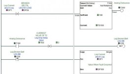
You are waiting 3 seconds after the motor has started before monitoring for a broken belt, but you will set the alarm bit if the current drops below the setpoint for even a split second. You might try adding a very short delay before setting the alarm to ignore any possible false readings. (Rungs 1 and 2 in my example)

The first thing I would do is use the rising edge of the broken belt alarm bit to copy the value of the analog input to a spare DF register. This will tell you what the analog value was that tripped the alarm. (Rung 3 in my example)

🍻

-Eric

Click1.jpg
 
We upgraded the HMI this winter & had to wait until a week ago to try it out.
Was the PLC program also changed, or only the HMI panel? If only the panel, then those operator settings are prime suspects. Some may have got left out so the operator doesn't get a chance to set them. Check to see if DS13, DF24, and DF12 are getting properly set.
 
Stopping M3 and allowing the PLC to attempt another start shuts the whole process down, with a flag of "Broken Belt" telling us M2 current has dropped well below the normal current for this motor. Not true.
Thinking some more, the light bulb went on and I thought of fruit salad. If you use apples you can make an apple pie, or with cherries you can get a cherry pie. With both you only make fruit salad. I mean if you mix very fast PLC control with slow motor-starter device switching, you get neither fast nor slow, but a mixture that may sometimes cause switching "races".

For your STOP commands, you are using HMI inputs and PLC outputs, so the result will happen very quick, in one PLC scan or there about. But on Page 1, Rungs 3 and 4, you are looking at physical devices (motor starter auxiliary contacts or VFD control outputs?) and these will not switch in 1 PLC scan. In fact, it may be 10 or 50 or more PLC scans after a STOP command before X001 and X003 go from ON to OFF. That time difference will keep your T2 and T5 timers energized long after the PLC thinks that the motors should be OFF.

In other words, for the LEG Motor Broken Belt relay C29, it will be a race between the Anlog current DF1 and Timer comparison "TD2 >= 3". If Timer 2 stays on for several PLC scans (held on by X003 which has not switched due to the slow motor control relay), then DF1 may drop fast enough to set C29, before TD2 time = 0 as the timer resets.

Now during the motor shutdown, you could easily get a 0 or very low current before T2 or T5 drops out. That means the broken belt relays C29 and C30 (and also C27 and C28) could erronously get SET while the motors are stopping. To fix that little problem, put a NC "stop" for each motor in series with the X001 and X003 on Page 1, rungs 3 and 4, to kill the timers the moment that the PLC goes into STOP mode for any motor.

You may need the same type of fix at other places where you are looking at the low current during shutdown of a motor.
 
Last edited:
When I left in my last post I was toying with immediate input from M2 aux contact but didn't think that would be quick enough yet. I've had to be sociable since, and will look at suggestions in the morning. I think you have me headed in the right direction by the looks of it. Thank you.
 
Questions whose answers would help me to help you:
(1) Which motor is M2 (the one that caused the alarm): the Inside Leg, or the South Drag? I don't see anything called "M2" anywhere in these rungs. South Drag = M1, Inside Leg = M2, NW Auger = M3

(2) What are "S Drag Inp" X001 and "Leg Inp" X003? Are these auxiliary contacts from the respective motor starters that verify the motors are running? (I hope they are). Yes

(3) If X003 is your Leg Motor Starter ON input, then on Page 2, Rung 5, how do you keep the 0 DF1 current (the moment the starter goes on) from enabling Stop Timer T4? At this point, how can we verify that DS13 (setpoint of Timer T4) is not 0 or close to 0? If DS13 is less than the time to get the motor up to speed, then this will cause a premature shut down. Is DS13 set, or changed from the operator panel? Where do you check to see that DS13 is not 0 and has been properly set? DS 12 & 13 are set from the HMI with min & max values set in that software. The screen for this is password protected.

I assume that the Broken Belt alarm happens on Page 8, where the broken belt relays C29 and C30 get SET or latched on. The things keeping them from NOT getting latched on are:

(A) DF1 must be the current for the Leg Motor. Is it, or did it get mixed up or swapped with DF2? These are correct

(B) T2 timer value <= 3 and DF1 current low will cause Leg Broken Belt C29. Is T2 enabled even when the Leg Motor is OFF? No. If so, the Leg Motor starter contact could be stuck ON, causing Input X003 to stay on, or X003 and X001 have been accidently swapped, so that they are monitoring the wrong motors and controlling the opposite timers. You probably should add an alarm rung that checks X001 and X003 when the Drag and Leg are OFF. If either input stays on, it means that you probably have a stuck contact in the motor starter, or whatever device is switching X001 and X003. M1 & M2 are manually started and have hardwired interlocks outside of the programming. While not as good as an alarm, the HMI indicates a motor running when the inputs are closed. That and 0 amps showing for the motor current should be a flag, then again I may rethink that.

(C) The LEG and DRAG NO LOAD current values DF24 and DF12 must be set to something other than 0. I see where you calculate all the other current levels, but not those 2. Where and What sets DF24 and DF12? If either is 0, then that would cause a Broken Belt alarm. It seems that DF24 and DF12 should also be calculated and set on Pages 9 or 10, along with all the other DF calculated current settings. DF12 & 24 are set via the HMI and have preset Min/Max values.

(D) For the Drag Broken Belt relay C30, you are checking the current when Timer T5 >= 3. However, looking at Timer T5 on Page 1, Rung 4, its setpoint is "2", so does it keep running past 2? The timer continues to run. Maybe you changed it to prevent a trip. From this, I assume then that the Drag Broken Belt C30 probably did not get set, so M2 is actually the Leg Motor, and C29 caused your Broken Belt alarm.

Therefore, the problem is likely on Page 8, Rung 1, or within the the devices on that rung as outlined above in A through C: DS13, DF1, DF24, Timer T2, or Input X003.

I have inserted instructions in lines 3 (Y003) & 4 (Y004) page 1, so that current samples are stopped when those outputs are true.

The lower limits of current for Broken Belts are low enough, that once exceeded, all motors need to stop. These are set via the HMI and have a Min/Max value.


Thank you,
 
I have inserted instructions in lines 3 (Y003) & 4 (Y004) page 1, so that current samples are stopped when those outputs are true.
Idon't think that Y004 will work for the Drag.

You should use a NC for Y003 on Rung 3 for the Leg, and a NC for Y001 on Rung 4 for the Drag.

You also need to stop current sampling (and the Timer delays) after a motor STOP in other places. Here are the ones I see with a casual look:

Page 1 Rung 2; (race between X002 and DF2 at Drag Stop)
Page 2 Rung 5; (race between X003 and DF11 at Leg Stop)
Page 9 Rung 6; (race between X001 and DF2 at Drag Stop)
Page 10 Rung 9; (race between X003 and DF1 at Leg Stop)
Page 11 Rung 4 (race between X003 and TD3 at Leg Stop)

You may need to find a shortcut to avoid having to fix all these places.
 
Last edited:
If you used Y001 for the Drag, then I am not surprised that it does not work.

You should use a NC for Y003 on Rung 3 for the Leg, and a NC for Y001 on Rung 4 for the Drag.

You also need to stop current sampling (and the Timer delays) after a motor STOP in other places. Here are the ones I see with a casual look:

Page 1 Rung 2;
Page 2 Rung 5;
Page 9 Rung 3;
Page 10 Rung 9

Not what I said, but it is what I did.:nodi:
It is MD and I only get minutes at a time. I agree on the others. Thank you.
 

Similar Topics

Hi all, I'm connecting several 4-20mA sensors together in parallel (only one shown below) The enclosure is ABS plastic with metal backplate DAQ...
Replies
5
Views
273
Problem: Our PLC can only output 4-20mA, but the actuators it needs to control, modulate based on a 0-135Ohm signal. Buying 4 or 8 individual...
Replies
7
Views
275
What's your go to 4-20ma isolator. I've got some 4 wire 4-20ma from several flow meters and scales that I would like to isolate before it gets to...
Replies
10
Views
1,692
Hi, I need to read three 4-20mA signals from a DCS(ABB) in a remote 6 channel analog input module with RS485 modbus port. When I connected...
Replies
2
Views
486
Hello this is my first post. Looking forward to being more involved in this community to learn and hopefully help others. Any help or guidance...
Replies
7
Views
790
Back
Top Bottom