Using an SCP instruction with a 1769-IF8 Analog Module

lsam

Member
Join Date
Jun 2013
Location
Reedsburg, WI
Posts
79
Could someone tell me which of the available tags in a 1769-IF8 analog module is typically used for the output of an SCP instruction. I am currently using the following tag for the input.

Local:5:I.CH0Data

Any Good thoughts anyone?
icon7.gif
 
I am getting a reading of -2 and I would have thought to have seen a reading of somewhere in the neighborhood of about 10 to 12.

This instruction is for reading the amount, in Amperage, of dc being used by either a 12vdc or 24vdc motor. I am using a transducer with an output scale of 4-20ma. The transducer is connected to a 24vdc - 100amp power supply. The SCP instruction is scaled from 0 - 50. The 12vdc motors typically draw about 12-15amps and the 24vdc motors typically draw about 8-10amps. That's why I was hoping to see a reading of about 10-12 instead of -2.
 
I tried changing the "scaled_Max" value from 50 to -50 and now I get a positive 2 reading. Does anyone have any idea why this happened? I ran the #8761 Belden shielded cable just like was suggested in the analog module manual, connected the black wire to the (-) output terminal on the transducer and the V/Iin0(-) terminal on the module. Then I connected the clear wire to the (+) terminal on the transducer and the Iin0(+) terminal on the module. Lastly, I connected the drain wire, on the module end of the cable only, to chasis ground(the closest thing to an earth ground since this equipment is mobile). This is not the power Supply negative.

If I decrease the "scaled_Max" value to (-)100, the resulting output value increases to "5".

Is this normal or what?
icon9.gif
 
Post your program, zip it first and someone with the software can take a look.

Tell the forum how the transducer is scaled 4ma = ??, 20ma = ?? in engineering units.

If you can't post the programming then post a snap shot of how you have the card configured and your SCP instruction.
 
Is the transducer 2 wire only?
If so it will need 24v supply.
+24v --> + of transducer
- of transducer --> + AB module input.
- of AB module --> Neg of 24v.

Look at the raw value from the AB card?
What is the value?
 
No. It's a 4-wire Automation Direct AcuAmp DCT200-42-24-F Fixed Core DC Transducer. I'll post a snapshot of the module configuration, the instruction, and a snapshot of part of the actual program shortly.
 
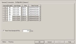
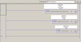
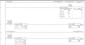
Here are three attachments including module configuration tab, SCP Instruction, and a sampling of the code that I am working with. The company's laptop does not the availability of zipping a file but at least I can take screen shots and it doesn't lockup half way through the uploading/downloading process. Just looking for the positive things!

icon11.gif
 
Oops! I forgot the attachments!

Here are three attachments including module configuration tab, SCP Instruction, and a sampling of the code that I am working with. The company's laptop does not the availability of zipping a file but at least I can take screen shots and it doesn't lockup half way through the uploading/downloading process. Just looking for the positive things!

icon11.gif


1769-IF8 configuration.JPG SCP Definition.jpg Sample Code.jpg
 
Being that this is my first solo project since leaving the classroom this past Spring, I'm at a loss for an explanation.

Isn't the input range supposed to be 4-20ma since that's what the transducer's output is? Also,isn't the filter supposed to be set to 60Hz for the good ole USA? Is the Data Format wrong too - Engineering Units?
 
All of your enabled channels are set to -10 to +10 Volts. The only settings for 4-20 ma are on disabled channels. You have indicated that you are using channel 0. It is set to -10 to +10 volts.
 

Similar Topics

Hello everyone, I have a little problem converting a 4-20ma signal to display a temp, reading on a PanelView. I have a RTD wired into a...
Replies
9
Views
5,633
I have a project to automate four generator sets. The system will monitor and store the load demand of the factory. Once there's Power outage, the...
Replies
0
Views
58
Adding ethernet equipment to an existing panel that has none. We have some solid ethernet cables coming from other remote cabinets that I plan to...
Replies
3
Views
119
I'm trying to control a device via MODBUS RTU and the ModbusRtuMasterV2_PcCOM in Twincat 3. I've configured a device with the right com port and...
Replies
7
Views
221
Hi, I'm trying to use the IO Device Library (Product Versions) which is configured to work with the 1756-EN4TR & 1756-EN2TR but my system uses...
Replies
0
Views
59
Back
Top Bottom