You are using an out of date browser. It may not display this or other websites correctly.
You should upgrade or use an alternative browser.
You should upgrade or use an alternative browser.
Using an SCP instruction with a 1769-IF8 Analog Module
- Thread starter lsam
- Start date
bernie_carlton
Lifetime Supporting Member + Moderator
I would think the output of the SCP would be sent to DCT_200_1_Current at least by what I see in the code following the SCP.
Greg Fowlds
Member
For the AB module set to 4-20ma and engineering values at
Local:5:I.CH0Data
4ma = 3200
20ma = 21000
You should have about 3200 with no power flowing through the current transducer.
If this is not the case then look at the wiring.
Turn off your scale instruction (put a normally open contact in front that is always open)
Look for the input values in the range above.
Swap the input wires over to see the effect.
Concentrate only on the raw input Local:5:I.CH0Data
Greg Fowlds
Member
OK I see it.
You have 4000 input
Set Scale
Input Min = 3200
Input Max = 21000
Try those values.
You have 4000 input
Set Scale
Input Min = 3200
Input Max = 21000
Try those values.
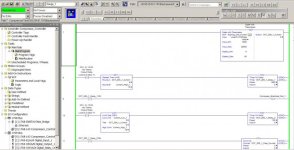
The next few rungs of code after the SCP instruction are for stopping the motor circuit should it draw too much amperage. I only need the SCP instruction to display digitally on the PanelView Plus 600 the amount of current passing through the motor circuit. Then using values displayed there to dial in a particular value at which to stop the motor circuit when passing too much amperage.
Ken Roach
Lifetime Supporting Member + Moderator
Hold on, STOP, take a step back and a deep breath.
You have a basic problem that you have to correct before you can proceed.
The tag that you have entered as the output of the SCP Add-On-Instruction is "DCT_200_1".
The tag you probably meant to use, because it is used in the logic below, is named "DCT_200_1_Current".
That tag DCT_200_1 is an Alias to one of the configuration tags for the 1769-IF8 module, called "Local:5:Ch0.Range". You don't want to reconfigure the channel range selection during runtime !
Go back and delete the tag DCT_200_1.
Now change the SCP instruction so that the output is directed to DCT_200_1_Current.
After you have done both of these things, you can start troubleshooting your signal and your logic.
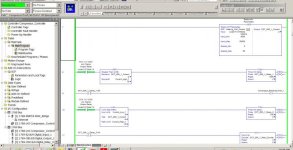
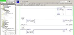
Since yesterday I made the adjustments recommended by Ken. So, here is a screenshot with the new values inserted. When I start the motor circuit the output goes to a negative (-) 2. Is there a way to make the output go positive without changing the 'scaled_Max' value to a negative value?
'Sample Code 1' shows online with PLC
"Sample Code 2' shows online with PLC with the motor circuit energized
As you can see in 'Sample Code 2' the output goes in the negative direction when the motor circuit is energized. Would this be caused by my motor power wire going through the transducer in the wrong direction? In other words, do I need to remove the wire passing through the transducer and put it back through the transducer in the opposite direction to remedy the output of the SCP instruction showing a negative number?


Mickey
Lifetime Supporting Member
Have you checked the current from your transducer to the input card?
Does it show something less then 4ma?
Does it show something less then 4ma?
Greg Fowlds
Member
It is not possible to see the values in the scale box in the screen shots.
Too low resolution.
Can you list them
Input=
Input Min=
InputMax=
Your Input_Min must be 3200
Your Input_Max must be 21000
NOT 4000 and 20000
If your input is less than the 4000 then the scaled output will be negative.
Too low resolution.
Can you list them
Input=
Input Min=
InputMax=
Your Input_Min must be 3200
Your Input_Max must be 21000
NOT 4000 and 20000
If your input is less than the 4000 then the scaled output will be negative.
Last edited:
Mickey
Lifetime Supporting Member
Your Input_Min must be 3200
Your Input_Max must be 21000
NOT 4000 and 20000
If your input is less than the 4000 then the scaled output will be negative.
Disagree, if the input is 4 to 20ma that is exactly what it should be. (4000 to 20000)
If he changed the values to 3200 and 21000 he would have to also change the scaled min and max. The SCP instruction does not clamp the scaled values, if the ma does go to 3.2ma the scaled values will go negative. Likewise if the ma goes to 21ma the scaled value will go above the scaled max.
Greg Fowlds
Member
According to the manual for the input card.
If it is set for engineering units then at
4ma = 3200
20ma = 21000
I will recheck those values shortly.
Can you see from the screen shots what the input value is?
If it is set for engineering units then at
4ma = 3200
20ma = 21000
I will recheck those values shortly.
Can you see from the screen shots what the input value is?
Mickey
Lifetime Supporting Member
The 3200 to 21000 represents the "full" range 3.2ma to 21ma not the normal operating range 4ma to 20ma. The raw data counts with a data format of "Engineering Units" follows the milliamp signal, it just adds three digits to it.
If you have a 4ma input you will have a value of 4000 counts, if you have a 20ma input you will have a value of 20000 counts.

If you have a 4ma input you will have a value of 4000 counts, if you have a 20ma input you will have a value of 20000 counts.
Last edited:
Greg Fowlds
Member
Ok, That explains it. Thanks.
So in this case is the input less than 4000?
That would give the negative value.
Exactly what is the input value?
So in this case is the input less than 4000?
That would give the negative value.
Exactly what is the input value?
Mickey
Lifetime Supporting Member
That would give the negative value.
Exactly what is the input value?
Exactly, I have ask a couple times in this thread if he has check it with a meter.
Similar Topics
Hello everyone,
I have a little problem converting a 4-20ma signal to display a temp, reading on a PanelView.
I have a RTD wired into a...
- Replies
- 9
- Views
- 5,635
I have a project to automate four generator sets. The system will monitor and store the load demand of the factory. Once there's Power outage, the...
- Replies
- 0
- Views
- 64
Adding ethernet equipment to an existing panel that has none. We have some solid ethernet cables coming from other remote cabinets that I plan to...
- Replies
- 3
- Views
- 124
I'm trying to control a device via MODBUS RTU and the ModbusRtuMasterV2_PcCOM in Twincat 3. I've configured a device with the right com port and...
- Replies
- 7
- Views
- 222
Hi,
I'm trying to use the IO Device Library (Product Versions) which is configured to work with the 1756-EN4TR & 1756-EN2TR but my system uses...
- Replies
- 0
- Views
- 60


