Messaging an ML1400

neos

Member
Join Date
May 2013
Location
Australia
Posts
37
Hi All,

I have been trawling around the threads for a while now and tried various things but to no avail.

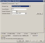
I am trying to use a read message in an RSlogix 5000 processor to get an array of the N7 [10] Ints from a ML1400. I am using CIP Data Table read, have configured the source and dest correctly i believe. The communication path is Enet, 2, 10.3.36.70. I can ping the IP address.

The error message code is 001F/0204 (connection in use)The ML1400 is also talking to a cpv600. I'm wondering if there's a resource setting I need to set. Any ideas would be appreciated!(y) Heres a piccy!

Neo

2014-11-26_160559.jpg
 
Welcome to the Forum !

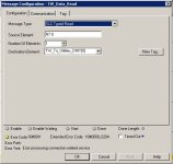
Change the Message Type to "SLC Typed Read".

CIP Data Table Read is for ControlLogix-to-ControlLogix messages using native ControlLogix tags.

Edit: I'm not totally sure if this will read 4 INTs or 8 INTs with the Number of Elements set for 4, and the Source (16-bit) and Destination (32-bit DINTs, I assume) being different.

Fill the destination with something nonzero and check to see what gets replaced.
 
Last edited:
neos said:
...I am trying to use a read message in an RSlogix 5000 processor to get an array of the N7 [10] Ints from a ML1400...

You are trying to read in an array of 10 elements, or words, from the N7 Integer data file, but you have "Number of Elements" in your MSG set to "4". This should be "10", as the Number of Elements refers to the source data type.

You have a destination tag "TW_To_Utilities_DINT" which, similar to Ken, I assume is a DINT tag? This is only good for 1 Integer.

If you were reading just 1x16bit source word into a 1xDINT destination, it will use 16 bits of the 32-bit DINT to store the word, and the other 16 bits are left unused.

If you were attempting to read 2x16-bit source words into a 1xDINT destination, it will not make the 32-bit DINT into 2x16-bit INTs and store the 2 words separately. The DINT is accessed and processed at the 32-bit level only. You would have to make the DINT an array of 2xDINT i.e. DINT[1].

For 10x16-bit words, you would need an array of 10xDINT. But each DINT uses 32 bits of memory, using 320 bits of memory to store 160 bits worth of data, wasting 160 bits of memory, which is half the memory used.

I know, the sin of it!

But it just shows how wasteful DINTs are while storing INT data, or SINT for that matter.

A better solution is to use the INT data type. An INT array packs its members contiguously. The first 2x16-bit words go into a 32-bit memory location, and so on. So a 10xINT array will use up 5x32 bits of memory, and not 10x32 bits, using only the required 160 bits of memory. Also, by using the INT data type, it makes it clearer as to what the tag, or array, is supposed to store.

Of course, this is efficient memory storage, not execution. It doesn't make execution any faster, but it can make it slower...

The Logix processors, being 32-bit native, when reading one of 2 packed INT values, have to read the 32 bits used by the 2 INTs, "parse" out whichever 16 bits it doesn't want, and then present the resultant 16-bit INT value. If an INT is used with an ADD instruction, it requires 260 bytes of memory just to access it, compared to just 28 bytes for a DINT. To execute in the ADD instruction, the INT takes 3.49us, compared to a DINT's 0.26us.

So while it saves you space, it slows you down. It's a trade-off I suppose?

Anyway, enough blathering...

So instead, you would have an array called "TW_To_Utilities_INT[9]". Enter the first element of the array into the "Destination Element" e.g. "TW_To_Utilities_INT[0]". Now your N7:0 - N7:9 Integers will each have a snug fitting home to go to.

Lesson for the day...

In Logix controllers, use SINT or INT data types when communicating with external devices that do not support DINT values.

Regards,
George
 
Thanks Ken. Changed it to typed read, set the array to 1 in length just for now until comms is sorted. The destination array is not being written to as yet. Still getting the same error. I will search the interwebs to see if I can find more info. Any other thoughts would be appreciated.

Geospark, I know the mapping is not right from the beginning, but its set at the moment just to get something across, its the least of my problems at the moment. Thanks though! (y)

2014-11-27_085354.jpg
 
Last edited:
The setting of "4", as it was, would not have worked to a single DINT, that was my main point. The use of INTs was more advice than necessary.

While the firmware anomaly mentioned here is specific to an SLC5/05, the settings for the Ethernet Channel 1 for the MicroLogix 1400 might be worth a try?

35243 - MSG: 16#001f with Extended Code16#0000_0204
Access Level: TechConnect

p.s. That Technote was only updated this month, so something is pretty new in there?

G.

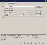
Hi Geospark, no probs. I dont have the access level to that tech note. I am wondering though as the messaging thinks its accessing an SLC but its really an ML1400, that i may need to specify the source port of the ML1400, if so i assume its 0,1 (slot 0 channel 1)?
 
Actually that Knowledgebase document recomments NOT adding a "1, 0" to the end of the CIP path, and it's specific to the SLC-5/05 operating system.

You do that with many CompactLogix targets because you're specifying a CIP path from the Ethernet daughtercard to the Virtual Backplane (Port 1) and the CPU (Slot 0). That's also always done with ControlLogix, where the Slot number is where the CPU is located.

But with the MicroLogix 1100 and 1400 and SLC-5/05, and even with the new 5370 series CompactLogix, the IP address of the target device should be the last element in the CIP Path.

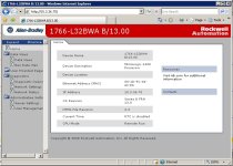
Are you 100% sure the MicroLogix 1400 is at the target IP address ? You've verified it with RSLinx and with a Web browser ? PING is nice, but all it does by itself is verify that there's something there, not what the thing is.
 
neos said:
...I am wondering though as the messaging thinks its accessing an SLC but its really an ML1400, that i may need to specify the source port of the ML1400, if so i assume its 0,1 (slot 0 channel 1)?

That's a negative!

The Ethernet port is built-in to the MicroLogix 1400, SLC 5/05, etc. There is no backplane, or module slot number to go through first - the wire is on the port directly. The port is as good as a stand-alone Ethernet port, containing its IP address, etc. within. So when pointing to them, their IP address is all that is needed at the end of your path to reach the Ethernet port. This goes for any built-in Ethernet port really, such as the older PLC-5's built-in ports.

Sorry, Ken has posted similar.

Error 16#204 is an "Unconnected Message Timeout". This is generated when a message fails to make the connection with the other device, but it did "find" the other device. If you look at the screenshot, there is no "Error Path" message, only the "Error Text". This means there isn't an issue with the path, but more an issue with the device at the end of the path. i.e. it found it, but it just didn't respond correctly, or in a timely fashion. I think the message timeout is 30 seconds, but I'd have to look that up to be sure?


G.
 
Last edited:
Are you 100% sure the MicroLogix 1400 is at the target IP address ? You've verified it with RSLinx and with a Web browser ? PING is nice, but all it does by itself is verify that there's something there, not what the thing is.

Yep no problems accessing the PLC. As this is a plant wide network, I have asked IT to make sure that all ports are available on that subnet. Will keep yous posted!

2014-11-27_095141.jpg
 
Last edited:
I was wondering about the connection count in the ML1400? It has 16 In and 16 Out, but the fact you just browsed to it proves it has at least 1 spare In connection?

The comms buffers are 8 In and 4 Out. Of which it will use 1 of each for the MSG In and reply to the Logix controller. While the outgoing message buffer queue is unlimited. i.e. it will wait until there is a buffer available, this could be getting hammered by the PV600, if it's polling large amounts of data at a high cyclic rate, possibly timing out the incoming MSG request for data? Probably not, but you'd never know.

Can you plug the PV600 off the network temporarily and attempt the MSG to rule this out?

I'll leave you in Ken's capable hands while I'm off to bed!

If you don't get sorted, I'll have a look again tomorrow.

p.s. the thing I wanted you to check from the Technote was the HTTP and SNMP settings for the ML1400 channel 1 Ethernet port configuration.

Night,

G.
 
Well thanks guys and appreciate all the efforts so far! I have just been talking to IT, and the PLC I am attempting to message with does not have the gateway configured, so it will see the micrologix but wont communicate. This PLC 10.3.41.20, ML1400 10.3.36.70. As this is a pharmaceutical plant, I need to schedule another day to make this change and do a change control. But will keep yous posted of the outcome. Thanks again! 🍻

NEO
 
Last edited:
Reading all the above posts, sounds as if you are almost there.
I have an ML1400 put in last year, and all worked between a PLC5 and ML1400 and SCADA for comms, but when I wanted to access it from my desk, I could not as that subnet was incorrect.
Like you, I had to schedule a task on a down day to go in, change the subnet and gateway and do a power cycle, and hey presto, it worked!
Best of luck......🍻
 

Similar Topics

Good morning all. Does anyone know where a sample program is located to message data to and from a Banner VE Series camera from a ML 1400? I am...
Replies
32
Views
12,145
Hello, I am trying to send descrete I/O data between 2 Micrologix 1400 PLC's using messaging instructions. Can anyone tell me if I have to use an...
Replies
3
Views
2,347
Been a long time since my last post and I was just learning even what a PLC is. Since then I have been fortunate to work with some great guys and...
Replies
22
Views
6,819
Hi All, I was wondering if it is possible to send ASCII commands via Ethernet messaging with a ML1400? I have to send instructions to and from a...
Replies
5
Views
3,662
I am attempting to map registers from N10 in Micrologix 1400, to Modbus addresses at a customer’s PLC, over an Ethernet connection. All the...
Replies
8
Views
3,940
Back
Top Bottom