ML1400 to Banner VE Camera messaging

Exporting the RSS project as a PDF (print to device [Microsoft Print to PDF]), and posting that PDF here, will make it available to more people; use [File] => [Report Options ...] to ensure all the data are in the PDF.
 
I have attached the file as a PDF. I was going to wait until I got it working and cleaned up but I have no problem with posting what I have now. Maybe someone can see the error in my ways. I had to deselect some of the report options to get it under the required size.
 
I also wanted to say after the Unnown Error e1, I went back to the manual to set up the messages per their instructions. I did not change the 500CPU Read/Write to PLC5 Read/Write as the manual said and when I changed the Write message to be 115 elements in size per the manual I got the following error - "ERROR: Transfer length may not exceed 103 elements for this Local Address." The N14 file in my program is 115 elements in length, so not sure why that error came up.
After I changed it to PLC5 per the manual that error went away. I will change them all to PLC5 Read/Write and see how that works and will update the thread afterwards. Thanks for everyone's input and assistance so far!!
 
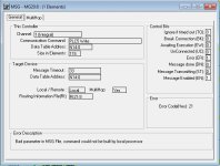
Just wanted to give an update. I changed the message instructions to PLC5 Read/Write and set them up per the Banner Camera manual and now I am getting an error that says - "Bad parameter in MSG File, command could not be built by local processor".

See attached screen shot.

2022_06_08_15_29_23_RSLogix_500_BANNER_CAMERA_MESSAGING.jpg
 
If following the VE manual's examples for PCCC gives no joy, then I can't help but think Modbus would be more reliable.


Misc comments; feel free to ignore.

I think most if not all of the [XIC B3:1/0] instructions after rung 0001 in LAD can be removed; same for [XIC B15:3/0] after Rung 0026. In fact, I think almost any rung with an [XIC MG20:x/DN] instruction should not need most of the other logic currently on that rung, because those MG20:x/DNs will not become 1 unless everything else before it becomes 1 as well.

That said, (A) I don't know much about this process, and (B) perhaps B3:1/0 changing to 0 is a way to stop the sequence.

There is nothing to handle MG20.x/ER becoming 1, but maybe you did not get there yet.

Rungs 0000 and 0001 could be

XIC B3:1/0 BST XIO MG20.3/EN CLR N14:0 1
NXB MSG MG20.3
BND


but that is silly.
 
I’m sorry I don’t remember this better. A few years ago setting up some messaging in a ML1100 or ML1400, I selected the wrong message type and developed with it for a while. When I tried to fix it, I was unable to get it to compile. It might have been the same error you see.

My fix was to completely delete and recreate the MSG instruction plus at least one of the MG or RI data files. I only had two messages so it wasn’t as much work as it would be for this project. You might try branching off a save, deleting the messages and data files, then create the files and a message again.

I might have found a thread here at that time with some insight on that from Ken Roach, but maybe not. That happens so often on other topics, I might be imagining it for this.

About multihop, I just pulled up a ML1100 example to confirm. Even though multihop is selected, there is a single channel 1 to EtherNet/IP device hop defined on the multihop tab. I don’t recall why, but I think I have always had to do it that way on a MicroLogix.
 
Dont worry about pylogix, you are not his target. But it would be nice if Pylogix can do PCCC.

Unfortunately I cannot open your RSS file. I only have v8.3 and it is small and nimble ( 30MB) vs 1GB of recent versions.

I did look at the PDF file, but it's not something I want to dwell into with time.

It's wrong approach when you are trying to establish comm.

Simplify it by just having one READ msg in your prog and see if you can read the ACK & Output register, specifically the Ready bit.

Screenshots of Camera settings would be helpful too.
 
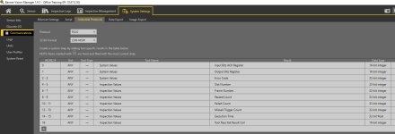
I changed the logic so there was one read instruction and it was working on getting the camera ready bit. I added a single write instruction to try to change the Product Number and it showed Done on the message with no errors but I did not see the Inspection Number change in the camera itself. I attached a screen shot of the camera industrial protocols tab and a screenshot of the program showing the messages indicating done. I tried writing N14:1 to the camera with 2 elements and it showed done. But then when I read the N7 file from the camera I am not getting the Inspection Number reading out. I also tried writing N14:1 to L9:0 in the PLC and writing that to the camera at N14:1 and still no inspection number showing up, and no errors either.

Banner Camera Protocols.jpg Message Status.jpg
 
so you are able to read now, but you jumping the gun with changing the product.

Simplify it with a simple trigger write, that is bit#2 of N14:0, not N14:1 and see if its triggered.

Wait for ready.
Set trigger input bit to 1
Wait for Trigger ACK bit go to to 1.
then set trigger input bit to 0.

Only one input bit can set at a time.
 
Last edited:
I want to say thanks to all that helped or offered help. I now have the camera and PLC communicating and transferring data as needed. I just have to work out the particulars on the camera pass/fail bits and figure out how to do the program number change.
 
You are welcome! good to hear you got the comm working.

Can you save your simplified program RSS to the (Library and/or Archived format) and see if I can open it with v8.3.
 
I got the communication working but I cannot get it to read the current inspection number. I can change the inspection number but it isn't reading the active inspection number. I saved the program as a "SLC" file and zipped it. See attached.
 
I was able to open the program. However, it's a mess and you are not taking my advice again. Do you really need to worry about MES, SAP, Climate stuff.

Your goal at this point is is write the product change to the camera, follow page 214.
 
If you notice the bit in the main program B3:0/0, that blocks out all of the routines except for Ladder 4, where I am trying to send and read the camera inspection number. Yes the program is messy right now because I was using the other ladders to try different things BUT those are blocked out.
 

Similar Topics

Hello, I am new here and have been working with PLCs for a few years now. I have been tasked with setting up a Micrologix 1400….. to a Cmore 10...
Replies
10
Views
499
Hi, We may of finally received out first v21 ML1400. IP address set, proceed to download standard file for our machines & at about the 80% mark...
Replies
10
Views
1,447
I have a Allen Bradely 1500 that has a cracked board. It still works but needs replaced (battery is no longer connected). To make migration easier...
Replies
10
Views
3,228
Hi, I've got a new project for a vacuum conveying system. We require to add another HMI to the existing system which will then feed 2 separate...
Replies
6
Views
1,832
Hi All I have connected a Keyence SR1000 to a Compact Logix PLC and am triggering the scanner and reading barcodes over Ethernet/IP, no issues...
Replies
2
Views
843
Back
Top Bottom