ML1400 Messaging

Can you post details about your setup?

IP Address of the ML1400
IP Address of the target device
How the networks are connected
Communication Command.

Basically everything you actually have and every setting of your MSG command.

I've really only done AB PLC to AB PLC type communications using the MSG command. So I don't have much experience with the setup beyond that specific type.
 
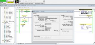
Can you post a screenshot of the MSG setup windows for the Modbus message? Is there a possibility that more than one message is triggered at a time?
 
Can you post details about your setup?

IP Address of the ML1400
IP Address of the target device
How the networks are connected
Communication Command.

Basically everything you actually have and every setting of your MSG command.

I've really only done AB PLC to AB PLC type communications using the MSG command. So I don't have much experience with the setup beyond that specific type.

IP of the PLC 10.10.201.15
IP of the server 10.10.201.16
Networks are using ethernet connections.
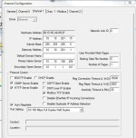
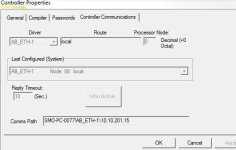
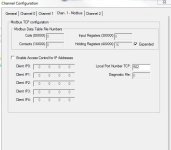
I will attach screenshots as best I can of everything.

Capture.jpg channel config.JPG controller prop.JPG channel config1.JPG
 
Based on what I can tell from your screenshots you are writing the data from N9:0 thru N9:15 to Modbus address 40001 thru 40016. Is that correct?

Are you sure that the data from your message is being received by the remote device? The alarm is saying that the PLC didn't receive any kind of reply from the remote device to let it know that it received the data.

I would make sure that your device is seeing the data. It might be easier to start with making one register work. Once you got that working add more to it.

I don't know what device you are communicating to but I have found that Modbus is a very loose standard. Not all devices work the same way. Many of the devices I work with require a coil to be set before it will accept a write. Then I have to monitor another register to see if the write commands were successful. Make sure you are not dealing with a situation similar to that.
 
if you just selected modbus tcp in the comm setup of the micrologix you will need to power cycle the 1400 to get modbus tcp to become active.
 
Based on what I can tell from your screenshots you are writing the data from N9:0 thru N9:15 to Modbus address 40001 thru 40016. Is that correct?

Are you sure that the data from your message is being received by the remote device? The alarm is saying that the PLC didn't receive any kind of reply from the remote device to let it know that it received the data.

I would make sure that your device is seeing the data. It might be easier to start with making one register work. Once you got that working add more to it.

I don't know what device you are communicating to but I have found that Modbus is a very loose standard. Not all devices work the same way. Many of the devices I work with require a coil to be set before it will accept a write. Then I have to monitor another register to see if the write commands were successful. Make sure you are not dealing with a situation similar to that.

I will try knocking down to one register tomorrow and see if I can figure things out.
I am not sure if the server is receiving the data or not, we are not seeing any change in the data tables so I will assume it is not.
I am communicating to a virtual server, i'm told a modbus slave server??
I contacted the programmer that wrote the code I was trying to duplicate and he will be stopping by next week. I was hoping to just figure this out on my own by then though as we love to do...
 
Just wanted to post a follow up now that it's all working!

I went back and had the internal programmer that set up the server and asked him to send me screenshots of the comm screens. I found a setting that was wrong and he found another after I questioned it. Changed those 2 and after lunch today tested the message and poof, right through over and over.
What a great feeling to have figured it out and be up and running.

Thanks for the help and giving me ideas to look at and check.

We are using Modbus slave as a server piece then the programmer is pulling information from there for his programs and HMI's etc.
Yeah, I know, not what i'd be doing either.... One day at a time.
 

Similar Topics

Good morning all. Does anyone know where a sample program is located to message data to and from a Banner VE Series camera from a ML 1400? I am...
Replies
32
Views
12,153
Hello, I am trying to send descrete I/O data between 2 Micrologix 1400 PLC's using messaging instructions. Can anyone tell me if I have to use an...
Replies
3
Views
2,351
Hi All, I was wondering if it is possible to send ASCII commands via Ethernet messaging with a ML1400? I have to send instructions to and from a...
Replies
5
Views
3,670
I am attempting to map registers from N10 in Micrologix 1400, to Modbus addresses at a customer’s PLC, over an Ethernet connection. All the...
Replies
8
Views
3,942
Hi all, Still pretty new to PLC's in general and brand spanking new to messaging. Trying to read from one ML1400 to another over ethernet. For...
Replies
2
Views
2,682
Back
Top Bottom