hgh speed counting

barry suydam

Member
Join Date
Mar 2011
Location
hamlet,nc
Posts
12
I am converting a machine from a micrologix 1100 to athe compactlogix 5069-L306ER controller. I have small disk about 0.930" and need to count at a rate of 1300 pcs/min. Can I do this and how? Most of my experience is with rslogix 500 and now I am getting into 5000 so it is a lot of new stuff for me.
 
If you were using a HS input in your ML1100 then you have to use a HS input in your Compactlogix , try to convert your program from RS500 to Studio 5000 and see what you get, personally I do not like the converter.
 
Counting 1300 "pieces" per 60 seconds presumably requires 1 off and 1 on state per piece.

That divides 60 seconds into at least 2600 intervals of 23 milliseconds each. The rule of thumb is that your input circuit and counting logic should be able to sense and solve twice as fast as the input can change.

Certainly a CompactLogix can run its inputs and a simple program at a 10 millisecond rate.

But if it were me, I would want a high-speed counter module to replace an embedded high-speed counter, so I would use a 5069-HSC2XOB4, which can handle a 1 MHz input signal.

I agree. Unless you are intimate with the device/process or have an o-scope to check it, it is hard to be sure how "square" those pulses really are.
 
Counting 1300 "pieces" per 60 seconds presumably requires 1 off and 1 on state per piece.

That divides 60 seconds into at least 2600 intervals of 23 milliseconds each. The rule of thumb is that your input circuit and counting logic should be able to sense and solve twice as fast as the input can change.

Certainly a CompactLogix can run its inputs and a simple program at a 10 millisecond rate.

But if it were me, I would want a high-speed counter module to replace an embedded high-speed counter, so I would use a 5069-HSC2XOB4, which can handle a 1 MHz input signal.

I have been successful at using the built-in HSC in the "fast" version of the 16-point DC input card, the 5069-IB16F. I'd have to look it up to be sure, but I believe its HSC is good for around 30KHz.
 
rupej, that's a fantastic point. I have not used the 5069 "medium speed" counters.

The User Manual says the ordinary 5069-IB16 counters can handle 500 Hz (probably sufficient for this application) and the fast 5069-IB16F can handle 30 kHz.
 
automation eng

Ken Roach
Actually the pieces are moving on a conveyor at 195 ft/min and the feeder rate controls the feed quant/min. the actual speed of the part is 1pcs/.025 secs.
At 25 ms I would have thought the 5069-16IB would be OK. I checked with Rockwell tech support and they suggested it was marginal which would explain why running thirty parts through the thru beam Sick sensor would register 15 pcs sometimes and 7 pcs on a repeat test. Whatever the case, I am opting for the HSC module to assure no guess work. overkill? Maybe, but I am up against the clock and need to get this system working.
 
When you got inconsistent counts in your testing, were you using the 5069-IB16's built in Counters, or just an ordinary input point with a CTU instruction ?

It's certainly your choice, but I would be very surprised if the 5069-IB16 built in counters couldn't keep up with a <100 Hz signal. The filter settings or the actual sensor signals are going to be important.
AS I am relatively new at the controllogix stuff, I didn't know the 5069-IB16's had the built in counters so I was just using the CTU instruction. Any suggestions would be helpful. Basicall, how do I use the builtin counters.
 
This technote has some good information regarding the filter settings for the 5069-IB16 inputs, as well as an interesting mention of a specific firmware upgrade which changes the way this module's filtering handles potential noise induced false signals...

1046736 - 5069-IB16 Inputs not Detecting Signals as Expected
Access Level: TechConnect

To use the embedded High Speed Counters open the Module Properties for the 5069-IB16 input module. This can be done by double-clicking on the input module instance under the I/O Configuration in your Logix 5000 project. Under the General category, open the Module Definition by clicking on the "Change" button. Here, under "Counters", you must first select away from "None" to at least "2" counters (2, 4, 8 may be selected).

OK the change and back at the previous screen you should now see the "Counters" category has been added. If you enter this category you will now see the settings for the number of counters you have enabled.

Note: When you enable counters in pairs (2, 4, 8), they will be using some of the available 16 input points for their signals, starting at point 0. For instance, if you enable 2 counters, then input points 0 and 1 are reserved for counter 0 and 1 functions, and so on up to point 7 (0-7 for maximum 8 counters enabled). When a counter has reserved an input point, the input filtering to be applied is adjusted under the Counters category, and not under the "Points" category.

Once counters have been enabled, and the Counters category created, the module-defined data type for the module will change to reflect the new Counter I/O tags. You can view these under Controller Tags, within the Configuration, Input, and Output tags for the module. You may use these tags to incorporate the counter(s) into your application.

Regards,
George
 
OK folks, I have set up my 5069-IB16 input module with four embedded counters. I have been on rockwell chat and done a bunch of research and both adventures have proved fruitless. The Rockwell library is so vast and convoluted my head is spinning. All I want to know is how do I program a sensor input signal into my new embedded counters. I originally wired my sick sensor to I:1/0 and tried to use a typical CTU. As posted earlier, not accurate. In leu of purchasing a HSC module I thought I would try to use the embedded counters in the input module. Got that set up fine. Now I assume I wire my sensor into the same input but I don't know how to program in the counter.
 
OK folks, I have set up my 5069-IB16 input module with four embedded counters. I have been on rockwell chat and done a bunch of research and both adventures have proved fruitless. The Rockwell library is so vast and convoluted my head is spinning. All I want to know is how do I program a sensor input signal into my new embedded counters. I originally wired my sick sensor to I:1/0 and tried to use a typical CTU. As posted earlier, not accurate. In leu of purchasing a HSC module I thought I would try to use the embedded counters in the input module. Got that set up fine. Now I assume I wire my sensor into the same input but I don't know how to program in the counter.

I would expect that a counter value will automatically appear in the Controller tag data assuming you set up the input card per Geospark's last post.

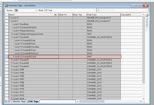
EDIT: I haven't looked into how to perform a reset, or if you can simply CLR the counter and I don't know whether it is required to do anything to the other tag members to enable counting or not, but your counter tag looks like this:

5069-IB16 Counter Mode.png
 
Last edited:
I've not used this newer module yet, but I would image that the embedded High Speed Counters are configured and executed in the module's hardware itself, similar to previous HSC modules, such as the 1769-HSC. You do not program them like you would a CTU instruction. Nor do you "program" signals to them.

If you are trying to input your sensor signal to Counter 0, for example, then you should have it wired to input point 0. Once the Counter is properly configured, it should automatically sense pulse transitions from the sensor and begin counting and displaying the count under the module-defined input tags.

p.s. that would be under the "Monitor Tags" tab, and not the "Edit Tags" tab that we see in the sample screenshot above.

Regards,
George
 

Similar Topics

Does anyone know what the data transfer rate for this series of CompactLogix PLC's? 1769-L24ER-QB1B to be exact. Cheers.
Replies
1
Views
98
Hello, I am trying to setup on plc so If I enter 60 jph (job per hour) it will send the vfd hertz based on what jph is entered by...
Replies
2
Views
160
Sigh, DeviceNet noob... I have a 1756-L55, with a DeviceNet module, and 10 PF700 all commanded with DeviceNet. One of the PF700's blew up...
Replies
3
Views
133
Do i have to use interrupt subroutine, or immediate read high speed input, for Unitronics Samba plc or reading only the correponding register in...
Replies
2
Views
124
Hi all, I'm having trouble solving a problem I've been working on for several months, and thought you might like a stab at it. The machine runs...
Replies
22
Views
951
Back
Top Bottom